Technical
NSC 29
July/Aug 18
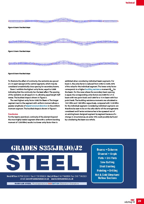
Figure 4: Beam 5 buckled shape
To illustrate the effect of continuity, the restraints are spaced
at 2 m apart (except at the central segment), which may be
considered unrealistically close spacing for secondary beams.
Beam 3 exhibits the highest unity factor, equal to 0.888
indicating that the continuity has the least effect. The spacing
of the restraints are all equal at 3 m, allowing equal length halfwaves.
The buckled shape is shown in Figure 5.
The next highest unity factor 0.882 for Beam 4. The longer
segment next to the segment with uniform moment allows a
greater amplitude of lateral torsional distortion in the uniform
moment segment. The buckled shape is shown in Figure 6
Conclusion
For the beams examined, continuity of the element beyond
the most highly loaded segment (that with a uniform bending
moment of 1200 kNm) results in a lower unity factor than is
exhibited when considering individual beam segments. For
beam 5, the unity factor is reduced from 0.982 to 0.840, 85%
of the value for the individual segment. The lower unity factor
corresponds to a higher buckling resistance moment Mb,Rd for
the beam. For the cases where the secondary beam spacing
is equal, the corresponding unity factors are 0.866 for a 9 m
beam with two point loads and 0.888 for a 15 m beam with four
point loads. The buckling resistance moments are calculated as
1351 kNm and 1385 kNm respectively, compared with 1220 kNm
for the individual segment. Considering individual segments can
therefore be seen to be on the safe side for all the arrangements
considered and if extra resistance has to be squeezed out of
an existing beam designed segment by segment because of a
change in circumstances, an extra 10% could possibly be found
by considering the beam as a whole.
Figure 5: Beam 3 buckled shape
Figure 6: Beam 4 buckled shape
/Member_design#Lateral_torsional_buckling_resistance
/Member_design#Buckling_resistance
/www.rainhamsteel.co.uk
link