Technical
Beam Length
26 NSC
(m)
July/Aug 18
Buckling resistance of
uniform members in bending
Richard Henderson of the Steel Construction Institute discusses the phenomenon of
lateral-torsional buckling.
Introduction
A grid of beams is usually divided into primary and secondary
beams and where there is no floor slab to provide continuous
support to the compression flanges, the secondary beams
provide discrete restraints to the primary. An end plate
connection to the primary beam web detailed in accordance
with the Green Book rules may be considered to provide a fork
end restraint. The secondary beams also apply point loads to
the primary and, for this type of connection, the loads are not
destabilizing. The system of point loads results in a shear force
diagram for the primary beam with constant values between the
point loads and a bending moment diagram made up of straight
lines (ignoring the effect of the primary beam self-weight).
In determining the resistance of the beam to bending,
especially in hand calculations, it is common to consider the
primary beam in segments defined by the incoming secondary
beams where the segments have defined end restraints and end
moments taken from the bending moment diagram of the full
beam. This approach corresponds to the conditions set out in
clause 6.3.3 of Eurocode 3 which deals with uniform members
in bending and axial compression and the effect of these two
actions in combination. Note 1 to clause 6.3.3(2) states: “The
interaction formulae are based on the modelling of simply
supported single span members with end fork conditions
and with or without continuous lateral restraints, which are
subjected to compression force, end moments and/or transverse
loads”. Taking the segments one by one is usually on the safe
side as the study described in the following sections shows. The
purpose of the study is to determine what effect continuity of
the beam beyond the segment being considered has on the
beam’s calculated bending resistance.
Beams studied
A series of loading arrangements on a 610 × 229 UB 140 was
examined. All the arrangements were chosen to result in a 3 m
segment of beam subject to a uniform moment of 1200 kNm.
The point loads were always applied at restraint positions and
beams of length 9 m and 15 m were considered. The loads
and restraint positions were chosen such that the lengths of
the segments were not always the same so that the half-wave
lengths of the buckled shape were uneven. The arrangements
are set out in Table 1.
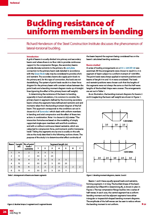
As an illustration, the bending moment diagrams for beams 2
and 6 (neglecting the beam self weight) are shown in Figure 1.
1200 kNm
1200 kNm
Figure 1: Bending moment diagrams, beams 2 and 6
Beams 1 and 3 have equally spaced loads and restraints,
forming segments 3 m long. The buckled shape of the beam
calculated by LTBeamN in determining Mcr is shown in plan in
Figure 2. The top compression flange buckles into a series of
half-waves. In each case, the central segment has a uniform
bending moment and the adjacent segments have either
triangular or trapezoidal-shaped bending moment diagrams.
The amplitude of the half-waves can be seen to reduce where
the bending moment is not uniform.
No of point
loads /
restraints
Table 1: Arrangement of beams and beam segments
Segment length (m)
1 2 3 4 5 6 7
1 9 2 3 3 3
2 9 2 3.5 3 2.5
3 15 4 3 3 3 3 3
4 15 4 3.5 2.5 3 3.5 2.5
5 15 6 2 2 2 3 2 2 2
6 15 4 3.5 2.5 3 2.5 3
3.5 3.0 2.5
3.5 2.5 3.0 2.5 3.5
Figure 2: Buckled shape: 3-segment and 5-segment beams 28
/Simple_connections#Flexible_end_plate_connections
/The_Green_Books
/Design_codes_and_standards#Eurocode_3_-_Steel_structures
/Steel_section_sizes