Technical
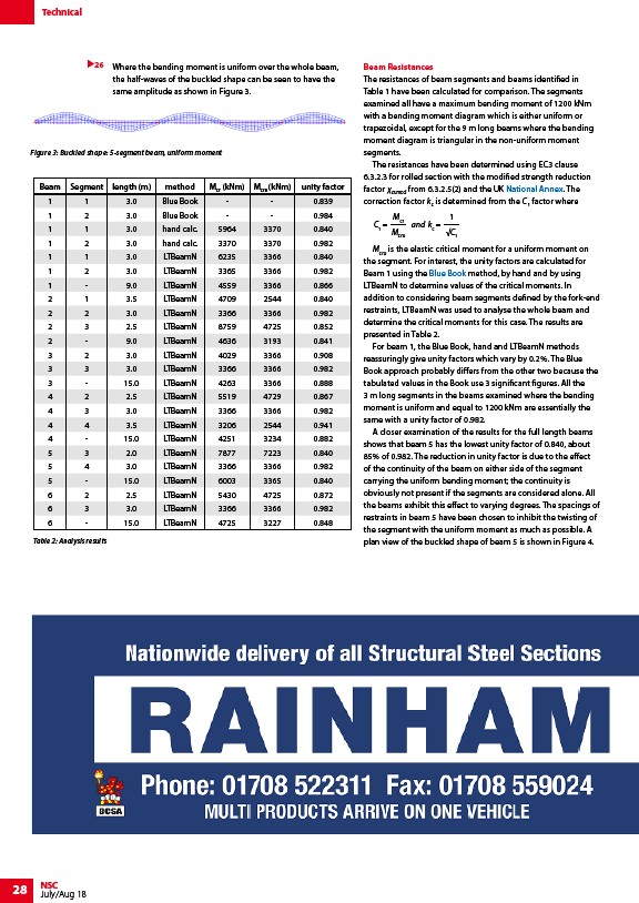
Figure 3: Buckled shape: 5-segment beam, uniform moment
Beam Segment length (m) method Mcr (kNm) Mcru (kNm) unity factor
1 1 3.0 Blue Book - - 0.839
1 2 3.0 Blue Book - - 0.984
1 1 3.0 hand calc. 5964 3370 0.840
1 2 3.0 hand calc. 3370 3370 0.982
1 1 3.0 LTBeamN 6235 3366 0.840
1 2 3.0 LTBeamN 3365 3366 0.982
1 - 9.0 LTBeamN 4559 3366 0.866
2 1 3.5 LTBeamN 4709 2544 0.840
2 2 3.0 LTBeamN 3366 3366 0.982
2 3 2.5 LTBeamN 8759 4725 0.852
2 - 9.0 LTBeamN 4636 3193 0.841
3 2 3.0 LTBeamN 4029 3366 0.908
3 3 3.0 LTBeamN 3366 3366 0.982
3 - 15.0 LTBeamN 4263 3366 0.888
4 2 2.5 LTBeamN 5519 4729 0.867
4 3 3.0 LTBeamN 3366 3366 0.982
4 4 3.5 LTBeamN 3206 2544 0.941
4 - 15.0 LTBeamN 4251 3234 0.882
5 3 2.0 LTBeamN 7877 7223 0.840
5 4 3.0 LTBeamN 3366 3366 0.982
5 - 15.0 LTBeamN 6003 3365 0.840
6 2 2.5 LTBeamN 5430 4725 0.872
6 3 3.0 LTBeamN 3366 3366 0.982
6 - 15.0 LTBeamN 4725 3227 0.848
28 NSC
July/Aug 18
Where the bending moment is uniform over the whole beam,
the half-waves of the buckled shape can be seen to have the
same amplitude as shown in Figure 3.
Beam Resistances
The resistances of beam segments and beams identified in
Table 1 have been calculated for comparison. The segments
examined all have a maximum bending moment of 1200 kNm
with a bending moment diagram which is either uniform or
trapezoidal, except for the 9 m long beams where the bending
moment diagram is triangular in the non-uniform moment
segments.
The resistances have been determined using EC3 clause
6.3.2.3 for rolled section with the modified strength reduction
factor χLT,mod from 6.3.2.5(2) and the UK National Annex. The
correction factor kc is determined from the C1 factor where
C1 =
1
C1
Mcr
Mcru
and kc =
Mcru is the elastic critical moment for a uniform moment on
the segment. For interest, the unity factors are calculated for
Beam 1 using the Blue Book method, by hand and by using
LTBeamN to determine values of the critical moments. In
addition to considering beam segments defined by the fork-end
restraints, LTBeamN was used to analyse the whole beam and
determine the critical moments for this case. The results are
presented in Table 2.
For beam 1, the Blue Book, hand and LTBeamN methods
reassuringly give unity factors which vary by 0.2%. The Blue
Book approach probably differs from the other two because the
tabulated values in the Book use 3 significant figures. All the
3 m long segments in the beams examined where the bending
moment is uniform and equal to 1200 kNm are essentially the
same with a unity factor of 0.982.
A closer examination of the results for the full length beams
shows that beam 5 has the lowest unity factor of 0.840, about
85% of 0.982. The reduction in unity factor is due to the effect
of the continuity of the beam on either side of the segment
carrying the uniform bending moment; the continuity is
obviously not present if the segments are considered alone. All
the beams exhibit this effect to varying degrees. The spacings of
restraints in beam 5 have been chosen to inhibit the twisting of
the segment with the uniform moment as much as possible. A
plan view of the buckled shape of beam 5 is shown in Figure 4.
26
Table 2: Analysis results
/Design_codes_and_standards#National_Annexes
/The_Blue_Book