U-frames in bridges
Bridge designers will be familiar with compression flanges restrained by u-frames.
David Brown of the SCI introduces the concept and illustrates the same principle
commonly found in the design of portal frames.
NSC 23
June 18
Engineers are always concerned with the buckling of elements
in compression and how restraint might be provided. In bridge
construction and (for example) a twin truss span, it may be
possible to brace between compression chords, as shown
in Figure 1, to form an enclosed box.
If bracing between the compression chords is to be avoided,
some other means of restraining the compression chord (or
compression flange, if the member is a beam) must be found.
There are many examples of older footbridges where a horizontal
cross member is extended laterally at deck level, and a diagonal
brace provided to restrain the compression flange, as shown in
Figure 2. People without an engineering background often think
the metalwork was provided to support pipework (and it was often
used for this), but the arrangement has a much more important
function.
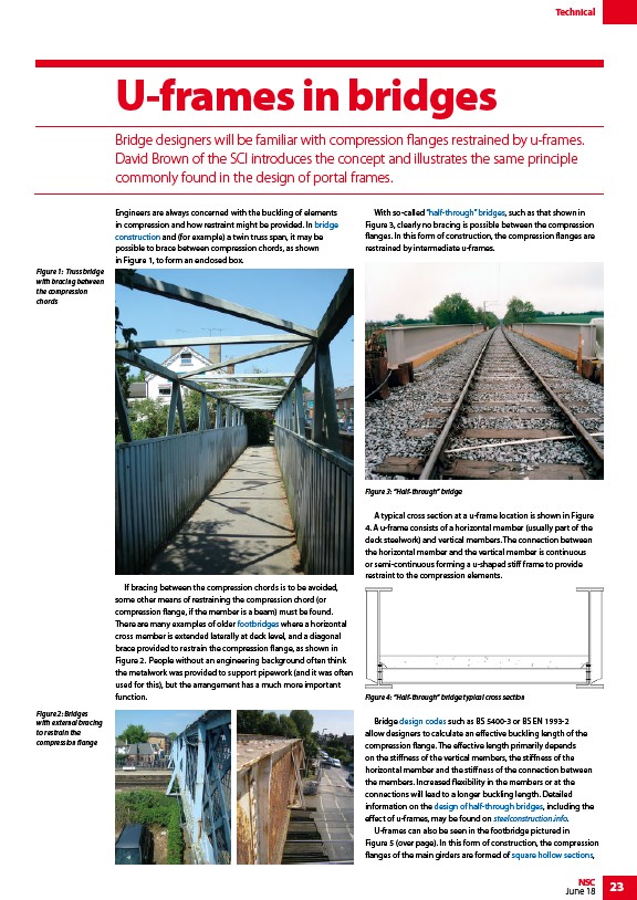
With so-called “half-through” bridges, such as that shown in
Figure 3, clearly no bracing is possible between the compression
flanges. In this form of construction, the compression flanges are
restrained by intermediate u-frames.
Figure 3: “Half-through” bridge
A typical cross section at a u-frame location is shown in Figure
4. A u-frame consists of a horizontal member (usually part of the
deck steelwork) and vertical members. The connection between
the horizontal member and the vertical member is continuous
or semi-continuous forming a u-shaped stiff frame to provide
restraint to the compression elements.
Figure 4: “Half-through” bridge typical cross section
Bridge design codes such as BS 5400-3 or BS EN 1993-2
allow designers to calculate an effective buckling length of the
compression flange. The effective length primarily depends
on the stiffness of the vertical members, the stiffness of the
horizontal member and the stiffness of the connection between
the members. Increased flexibility in the members or at the
connections will lead to a longer buckling length. Detailed
information on the design of half-through bridges, including the
effect of u-frames, may be found on steelconstruction.info.
U-frames can also be seen in the footbridge pictured in
Figure 5 (over page). In this form of construction, the compression
flanges of the main girders are formed of square hollow sections,
Figure 1: Truss bridge
with bracing between
the compression
chords
Figure 2: Bridges
with external bracing
to restrain the
compression flange
Technical
/Design_for_steel_bridge_construction
/Design_for_steel_bridge_construction
/Design_of_steel_footbridges
/Half-through_bridges
/Design_codes_and_standards
/Design_for_half-through_construction
/www.steelconstruction.info
/Steel_construction_products#Structural_hollow_sections
/Design_for_steel_bridge_construction
/Design_for_steel_bridge_construction
/Design_of_steel_footbridges
/Half-through_bridges
/Design_codes_and_standards
/Design_for_half-through_construction
/www.steelconstruction.info
/Steel_construction_products#Structural_hollow_sections