Commercial
17
are absorbed into a more traditional
rectangular three-storey element at the
tower’s western lower levels.
Three floors (first to third) cantilever
out by 4m to avoid a line of perimeter
columns that would obstruct a pedestrian
thoroughfare.
This cantilever is formed by a series
of 10m-long plate girders positioned
at first floor, each weighing 44t. The
installation of these members required
steelwork contractor William Hare to use a
250t-capacity mobile crane.
“Most of the remainder of our 9,500t steel
tonnage has been erected via tower cranes
that are positioned on top of the core,”
explains William Hare Senior Site Manager
Ben Burns, “apart from the 90t perimeter
columns which required a 90t-capacity
mobile crane to be brought to site.”
One Bank Street is due to complete
during 2019.
Soft cores One Bank Street adopts the familiar approach to office building construction of concrete core surrounded by steel
frame with some particular features. Richard Henderson of the SCI discusses some of the details.
The construction sequence at One
construction before the details of risers for
building services were finalised. This led to the
adoption of a “soft core” in a 4m zone on the long
east and west sides of the concrete core which
could be finalised later, bounded by a row of
steel columns.
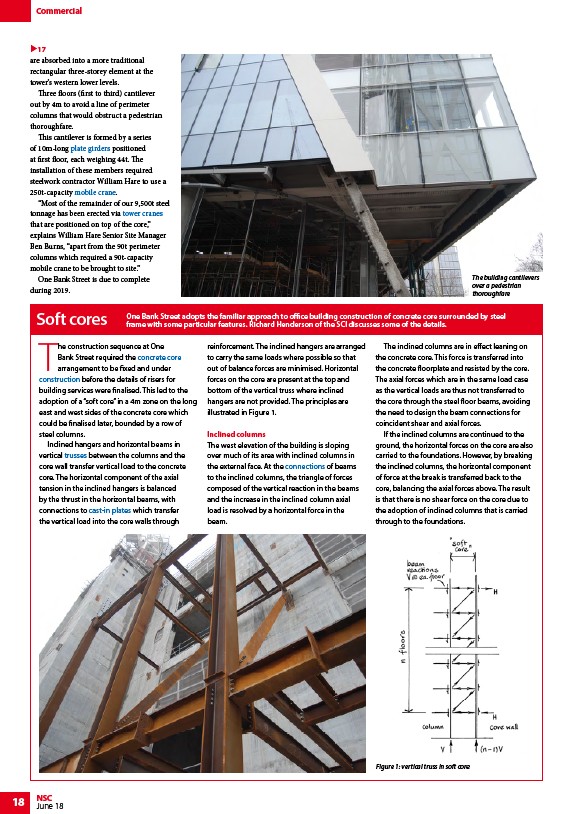
Inclined hangers and horizontal beams in
vertical trusses between the columns and the
core wall transfer vertical load to the concrete
core. The horizontal component of the axial
tension in the inclined hangers is balanced
by the thrust in the horizontal beams, with
connections to cast-in plates which transfer
the vertical load into the core walls through
18 NSC
Bank Street required the concrete core
arrangement to be fixed and under
June 18
reinforcement. The inclined hangers are arranged
to carry the same loads where possible so that
out of balance forces are minimised. Horizontal
forces on the core are present at the top and
bottom of the vertical truss where inclined
hangers are not provided. The principles are
illustrated in Figure 1.
Inclined columns
The west elevation of the building is sloping
over much of its area with inclined columns in
the external face. At the connections of beams
to the inclined columns, the triangle of forces
composed of the vertical reaction in the beams
and the increase in the inclined column axial
load is resolved by a horizontal force in the
beam.
The inclined columns are in effect leaning on
the concrete core. This force is transferred into
the concrete floorplate and resisted by the core.
The axial forces which are in the same load case
as the vertical loads are thus not transferred to
the core through the steel floor beams, avoiding
the need to design the beam connections for
coincident shear and axial forces.
If the inclined columns are continued to the
ground, the horizontal forces on the core are also
carried to the foundations. However, by breaking
the inclined columns, the horizontal component
of force at the break is transferred back to the
core, balancing the axial forces above. The result
is that there is no shear force on the core due to
the adoption of inclined columns that is carried
through to the foundations.
Figure 1: vertical truss in soft core
The building cantilevers
over a pedestrian
thoroughfare
/Steel_construction_products#Plate_girders
/Construction#Mobile_cranes
/Construction#Tower_cranes
/Concept_design#Concrete_or_steel_cores
/Construction
/Trusses
/Design#Concrete_or_steel_cores
/Simple_connections#Beam-to-beam_and_beam-to-column_connections
/Steel_construction_products#Plate_girders
/Construction#Mobile_cranes
/Construction#Tower_cranes
/Concept_design#Concrete_or_steel_cores
/Construction
/Trusses
/Design#Concrete_or_steel_cores
/Simple_connections#Beam-to-beam_and_beam-to-column_connections