Commercial
NSC 17
June 18
Dominic Munro.
The steel columns adjacent to the core
are part of a vertical steel truss system,
which transfers all the vertical loads to the
core. The diagonal members of the truss
are, in effect, hangers supporting the floor
below. The main advantage of this truss
system is that the load in the steel columns
is greatly reduced.
“We have estimated that approximately
600t of steel was saved as a result of this
idea. The concrete core benefits from the
additional vertical load as tensile stresses
from wind loading are reduced. The
continuous truss also means that there is
very little differential movement between
the steel and concrete elements of the core,”
adds Mr Munro.
Adjacent to the core, the building has
two large atrium spaces that are separated
by a floor slab at level eight, which is
supported from above by inclined hangers.
The lower atrium extends upwards from
level four to the separating slab, while above
the second atrium then proceeds upwards
to level 10.
The steel frame is primarily arranged
around the core with Fabsec cellular beams
radiating outwards on all four elevations to
create column-free spans of up to 14m to
the perimeters.
Many of these cellular beams have
in-built flexibility, as they have additional
holes for future services routing.
An exception to the column-free design
is the sloping western elevation, which
overlooks the River Thames.
From the top of level three to level 12, a
series of raking columns facetted on each
floor, create a feature slope which then
continues upwards less steeply to level 23,
via cantilevering floors, until level 23 where
the elevation becomes vertical.
Along this elevation, the structure’s
internal floorplate is no longer columnfree,
as at level four there are two lines of
internal columns. However, as the slope
decreases the size of the floorplate, there is
only one line of columns by level eight and
none are present by level 12.
According to Dominic Munro, each
floor along the raking façade has to resist
a horizontal compressive force which is
a function of the given floor’s load (plus
the effect of any additional change of
inclination).
This results in the building leaning onto
the core and pushing it towards the east.
“In order to mitigate this effect, we came
up with the idea of breaking the two corner
raking columns at levels where they come
near a vertical column, namely level 14 and
level four,” says Mr Munro.
“Where the breaks in the raking columns
occur, loads are transferred to nearby
vertical columns via transfer beams. This
has the double advantage of reducing the
force running down the raking columns,
and hence the forces leaning on the core,
and also creates a balanced system whereby
the transfer floors and the stability core are
subject to a symmetric set of forces with no
overall twisting effect.”
Although the raking columns continue
all the way down to ground level, they 18
Steel erection
progresses on the
structure’s upper floors
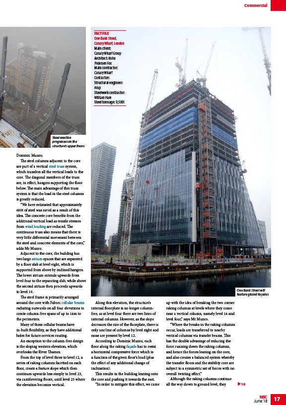
One Bank Street will
feature glazed façades
FACT FILE
One Bank Street,
Canary Wharf, London
Main client:
Canary Wharf Group
Architect: Kohn
Pedersen Fox
Main contractor:
Canary Wharf
Contractors
Structural engineer:
Arup
Steelwork contractor:
William Hare
Steel tonnage: 9,500t
/Trusses
/Design_codes_and_standards#Wind_actions
/Steel-supported_glazed_facades_and_roofs#Atrium_Roofs_and_Sky_lights
/Service_integration#Composite_beams_with_web_openings
/Facades_and_interfaces
/Trusses
/Design_codes_and_standards#Wind_actions
/Steel-supported_glazed_facades_and_roofs#Atrium_Roofs_and_Sky_lights
/Service_integration#Composite_beams_with_web_openings
/Facades_and_interfaces