Technical
26 NSC
June 19
A crude examination such as this neglects a proper
assessment of the stress ranges to which the bracing connection
details are subjected. The bracing members are usually designed
for wind loads and equivalent horizontal forces (EHF). These
forces may also be amplified by a factor based on the elastic
critical load factor of the building. Fatigue is a serviceability load
case and the load factor on the wind load is therefore equal to
unity instead of 1.5. Also, the EHF and amplification factor are
intended to allow for global imperfections and second order
effects respectively and are therefore not included in fatigue
calculations. The stress ranges for the fatigue check are therefore
significantly smaller than might initially be imagined.
Design Example
An example fatigue check on a connection detail for a bracing
member taken from the design example in SCI’s publication
P365 Steel building design: medium rise braced frames is
illustrative.
The ultimate design load in the bracing member from ground
to first floor is 539 kN. 60.9% of this force is due to wind load and
it includes an amplification factor of 1.17. The serviceability load
due to wind alone is therefore:
537.4
1.17
× 0.609 ×
1
1.5
= 187.2 kN
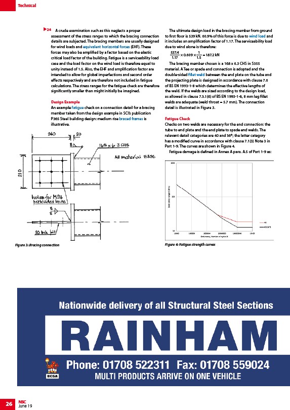
The bracing member chosen is a 168 x 6.3 CHS in S355
material. A Tee or spade end connection is adopted and the
double-sided fillet weld between the end plate on the tube and
the projecting plate is designed in accordance with clause 7.6
of BS EN 1993-1-8 which determines the effective lengths of
the weld. If the welds are sized according to the design load,
as allowed in clause 7.3.1(6) of BS EN 1993-1-8, 8 mm leg fillet
welds are adequate (weld throat = 5.7 mm). The connection
detail is illustrated in Figure 3.
Fatigue Check
Checks on two welds are necessary for the end connection: the
tube to end plate and the end plate to spade end welds. The
relevant detail categories are 40 and 36*; the latter category
has a modified curve in accordance with clause 7.1(3) Note 3 in
Part 1-9. The curves are shown in Figure 4.
Fatigue damage is defined in Annex A para. A.5 of Part 1-9 as:
24
Figure 3: Bracing connection Figure 4: Fatigue strength curves
/Braced_frames#Equivalent_horizontal_forces
/Fatigue_design_of_bridges#The_mechanism_of_fatigue
/Braced_frames
/Design_codes_and_standards#Wind_actions
/Welding#Fillet_welds