Technical
NSC 29
January 19
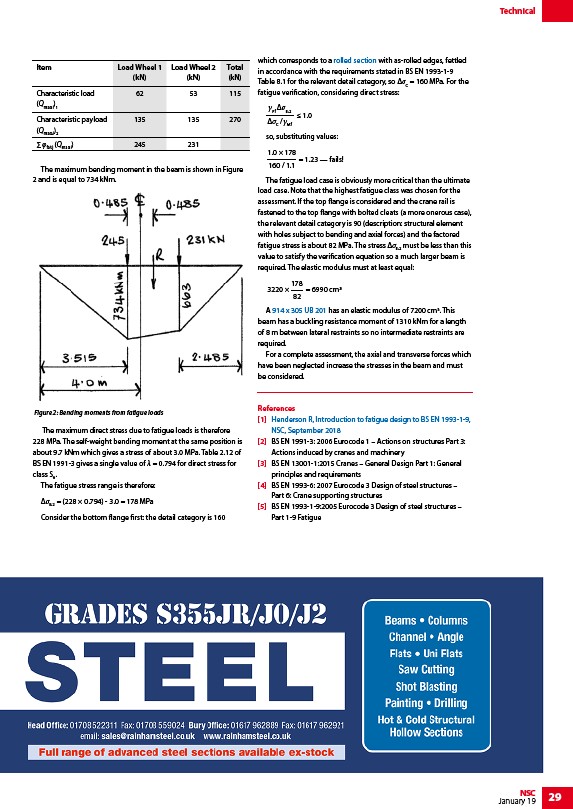
The maximum bending moment in the beam is shown in Figure
2 and is equal to 734 kNm.
The maximum direct stress due to fatigue loads is therefore
228 MPa. The self-weight bending moment at the same position is
about 9.7 kNm which gives a stress of about 3.0 MPa. Table 2.12 of
BS EN 1991-3 gives a single value of λ = 0.794 for direct stress for
class S6.
The fatigue stress range is therefore:
ΔσE,2 = (228 × 0.794) - 3.0 = 178 MPa
Consider the bottom flange first: the detail category is 160
which corresponds to a rolled section with as-rolled edges, fettled
in accordance with the requirements stated in BS EN 1993-1-9
Table 8.1 for the relevant detail category, so ΔσC = 160 MPa. For the
fatigue verification, considering direct stress:
Ff E,2
1.0
/C Mf
so, substituting values:
1.0 × 178
= 1.23 — fails!
160 / 1.1
The fatigue load case is obviously more critical than the ultimate
load case. Note that the highest fatigue class was chosen for the
assessment. If the top flange is considered and the crane rail is
fastened to the top flange with bolted cleats (a more onerous case),
the relevant detail category is 90 (description: structural element
with holes subject to bending and axial forces) and the factored
fatigue stress is about 82 MPa. The stress Δσ2 must be less than this
E,value to satisfy the verification equation so a much larger beam is
required. The elastic modulus must at least equal:
= 6990 cm
178
82
3220 ×
A 914 x 305 UB 201 has an elastic modulus of 7200 cm3. This
beam has a buckling resistance moment of 1310 kNm for a length
of 8 m between lateral restraints so no intermediate restraints are
required.
For a complete assessment, the axial and transverse forces which
have been neglected increase the stresses in the beam and must
be considered.
References
1 Henderson R, Introduction to fatigue design to BS EN 1993-1-9,
NSC, September 2018
2 BS EN 1991-3: 2006 Eurocode 1 – Actions on structures Part 3:
Actions induced by cranes and machinery
3 BS EN 13001-1:2015 Cranes – General Design Part 1: General
principles and requirements
4 BS EN 1993-6: 2007 Eurocode 3 Design of steel structures –
Part 6: Crane supporting structures
5 BS EN 1993-1-9:2005 Eurocode 3 Design of steel structures –
Part 1-9 Fatigue
Item Load Wheel 1
(kN)
Load Wheel 2
(kN)
Total
(kN)
Characteristic load
(Qmax,i)1
62 53 115
Characteristic payload
(Qmax,i)2
135 135 270
Σ φfat,j (Qmax,i) 245 231
Figure 2: Bending moments from fatigue loads
/Steel_construction_products#Standard_open_sections
/Steel_section_sizes
/NSC_Sept18-Tech.pdf
/NSC_Sept18-Tech.pdf
/www.rainhamsteel.co.uk
link