Commercial
20 NSC
January 19
throughout the scheme, but in areas
where new build meets retained
structure, the new slab corresponds to
the old.
In the old building, services were
accommodated below the steel beams,
but as the new areas have cellular
beams, allowing the services to be
placed within the steelwork’s depth,
there are areas where the services
transfer from one configuration to
another.
The one exception to the standard
7.5m grid pattern is the eastern
elevation of the building that spans
over the Liverpool Street Bus Station,
which has been closed temporarily
during the construction works.
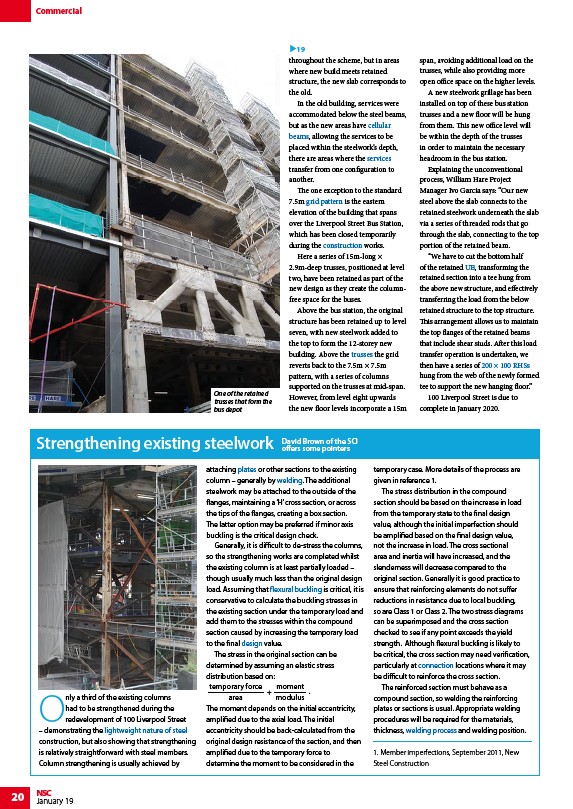
Here a series of 15m-long ×
2.9m-deep trusses, positioned at level
two, have been retained as part of the
new design as they create the columnfree
space for the buses.
Above the bus station, the original
structure has been retained up to level
seven, with new steelwork added to
the top to form the 12-storey new
building. Above the trusses the grid
reverts back to the 7.5m × 7.5m
pattern, with a series of columns
supported on the trusses at mid-span.
However, from level eight upwards
the new floor levels incorporate a 15m
span, avoiding additional load on the
trusses, while also providing more
open office space on the higher levels.
A new steelwork grillage has been
installed on top of these bus station
trusses and a new floor will be hung
from them. This new office level will
be within the depth of the trusses
in order to maintain the necessary
headroom in the bus station.
Explaining the unconventional
process, William Hare Project
Manager Ivo Garcia says: “Our new
steel above the slab connects to the
retained steelwork underneath the slab
via a series of threaded rods that go
through the slab, connecting to the top
portion of the retained beam.
“We have to cut the bottom half
of the retained UB, transforming the
retained section into a tee hung from
the above new structure, and effectively
transferring the load from the below
retained structure to the top structure.
This arrangement allows us to maintain
the top flanges of the retained beams
that include shear studs. After this load
transfer operation is undertaken, we
then have a series of 200 × 100 RHSs
hung from the web of the newly formed
tee to support the new hanging floor.”
100 Liverpool Street is due to
complete in January 2020.
19
Only a third of the existing columns
had to be strengthened during the
redevelopment of 100 Liverpool Street
– demonstrating the lightweight nature of steel
construction, but also showing that strengthening
is relatively straightforward with steel members.
Column strengthening is usually achieved by
attaching plates or other sections to the existing
column – generally by welding. The additional
steelwork may be attached to the outside of the
flanges, maintaining a ‘H’ cross section, or across
the tips of the flanges, creating a box section.
The latter option may be preferred if minor axis
buckling is the critical design check.
Generally, it is difficult to de-stress the columns,
so the strengthening works are completed whilst
the existing column is at least partially loaded –
though usually much less than the original design
load. Assuming that flexural buckling is critical, it is
conservative to calculate the buckling stresses in
the existing section under the temporary load and
add them to the stresses within the compound
section caused by increasing the temporary load
to the final design value.
The stress in the original section can be
determined by assuming an elastic stress
distribution based on:
+
temporary force
area
moment
modulus
.
The moment depends on the initial eccentricity,
amplified due to the axial load. The initial
eccentricity should be back-calculated from the
original design resistance of the section, and then
amplified due to the temporary force to
determine the moment to be considered in the
temporary case. More details of the process are
given in reference 1.
The stress distribution in the compound
section should be based on the increase in load
from the temporary state to the final design
value, although the initial imperfection should
be amplified based on the final design value,
not the increase in load. The cross sectional
area and inertia will have increased, and the
slenderness will decrease compared to the
original section. Generally it is good practice to
ensure that reinforcing elements do not suffer
reductions in resistance due to local buckling,
so are Class 1 or Class 2. The two stress diagrams
can be superimposed and the cross section
checked to see if any point exceeds the yield
strength. Although flexural buckling is likely to
be critical, the cross section may need verification,
particularly at connection locations where it may
be difficult to reinforce the cross section.
The reinforced section must behave as a
compound section, so welding the reinforcing
plates or sections is usual. Appropriate welding
procedures will be required for the materials,
thickness, welding process and welding position.
1. Member imperfections, September 2011, New
Steel Construction
Strengthening existing steelwork David Brown of the SCI
offers some pointers
One of the retained
trusses that form the
bus depot
/Steel_construction_products#Cellular_beams
/Steel_construction_products#Cellular_beams
/Service_integration
/Concept_design#Floor_grids
/Construction
/Trusses
/Steel_construction_products#Standard_open_sections
/Steel_section_sizes
/The_case_for_steel#Take_a_load_off_your_foundations
/Steel_construction_products#Flat_products_-_plates
/Welding
/Member_design#Flexural_buckling_.28only.29
/Design
/Simple_connections
/Welding#Processes