Mixed-use
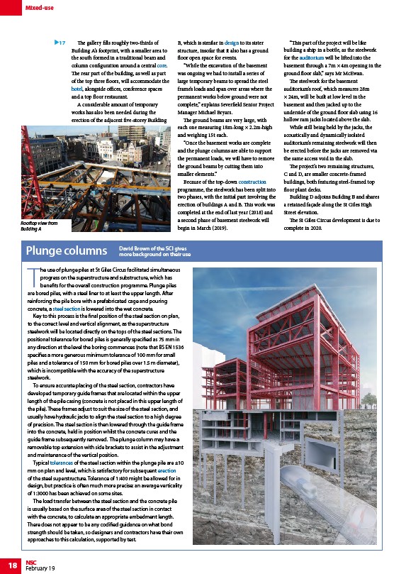
Rooftop view from
Building A
Plunge columns David Brown of the SCI gives
18 NSC
February 19
The gallery fills roughly two-thirds of
Building A’s footprint, with a smaller area to
the south formed in a traditional beam and
column configuration around a central core.
The rear part of the building, as well as part
of the top three floors, will accommodate the
hotel, alongside offices, conference spaces
and a top floor restaurant.
A considerable amount of temporary
works has also been needed during the
erection of the adjacent five-storey Building
B, which is similar in design to its sister
structure, insofar that it also has a ground
floor open space for events.
“While the excavation of the basement
was ongoing we had to install a series of
large temporary beams to spread the steel
frame’s loads and span over areas where the
permanent works below ground were not
complete,” explains Severfield Senior Project
Manager Michael Bryars.
The ground beams are very large, with
each one measuring 18m-long × 2.2m-high
and weighing 15t each.
“Once the basement works are complete
and the plunge columns are able to support
the permanent loads, we will have to remove
the ground beams by cutting them into
smaller elements.”
Because of the top-down construction
programme, the steelwork has been split into
two phases, with the initial part involving the
erection of buildings A and B. This work was
completed at the end of last year (2018) and
a second phase of basement steelwork will
begin in March (2019).
“This part of the project will be like
building a ship in a bottle, as the steelwork
for the auditorium will be lifted into the
basement through a 7m × 4m opening in the
ground floor slab,” says Mr McEwan.
The steelwork for the basement
auditorium’s roof, which measures 28m
× 24m, will be built at low level in the
basement and then jacked up to the
underside of the ground floor slab using 16
hollow ram jacks located above the slab.
While still being held by the jacks, the
acoustically and dynamically isolated
auditorium’s remaining steelwork will then
be erected before the jacks are removed via
the same access void in the slab.
The project’s two remaining structures,
C and D, are smaller concrete-framed
buildings, both featuring steel-framed top
floor plant decks.
Building D adjoins Building B and shares
a retained façade along the St Giles High
Street elevation.
The St Giles Circus development is due to
complete in 2020.
17
more background on their use
The use of plunge piles at St Giles Circus facilitated simultaneous
progress on the superstructure and substructure, which has
benefits for the overall construction programme. Plunge piles
are bored piles, with a steel liner to at least the upper length. After
reinforcing the pile bore with a prefabricated cage and pouring
concrete, a steel section is lowered into the wet concrete.
Key to this process is the final position of the steel section on plan,
to the correct level and vertical alignment, as the superstructure
steelwork will be located directly on the tops of the steel sections. The
positional tolerance for bored piles is generally specified as 75 mm in
any direction at the level the boring commences (note that BS EN 1536
specifies a more generous minimum tolerance of 100 mm for small
piles and a tolerance of 150 mm for bored piles over 1.5 m diameter),
which is incompatible with the accuracy of the superstructure
steelwork.
To ensure accurate placing of the steel section, contractors have
developed temporary guide frames that are located within the upper
length of the pile casing (concrete is not placed in this upper length of
the pile). These frames adjust to suit the size of the steel section, and
usually have hydraulic jacks to align the steel section to a high degree
of precision. The steel section is then lowered through the guide frame
into the concrete, held in position whilst the concrete cures and the
guide frame subsequently removed. The plunge column may have a
removable top extension with side brackets to assist in the adjustment
and maintenance of the vertical position.
Typical tolerances of the steel section within the plunge pile are ±10
mm on plan and level, which is satisfactory for subsequent erection
of the steel superstructure. Tolerance of 1:400 might be allowed for in
design, but practice is often much more precise: an average verticality
of 1:3000 has been achieved on some sites.
The load transfer between the steel section and the concrete pile
is usually based on the surface area of the steel section in contact
with the concrete, to calculate an appropriate embedment length.
There does not appear to be any codified guidance on what bond
strength should be taken, so designers and contractors have their own
approaches to this calculation, supported by test.
/Concept_design#Concrete_or_steel_cores
/Residential_and_mixed-use_buildings#Hotels
/Design
/Construction
/Leisure_buildings#Theatres_and_auditoria
/Steel_construction_products#Standard_open_sections
/Construction#Tolerances
/Construction#Steel_erection