Technical
NSC 29
May 18
In each case, the straight (black) lines in Figure 1 are the FE results, and
illustrate deflection at points along the supported beam. The irregular lines
show the measured deflections.
From Figure 1, it can be seen that the FE model was a good predictor of the
test results. The stress patterns at the fin plate connection are shown in Figure
2. As anticipated, the higher stresses are at the extreme bolt locations in the
fin plate. It should be noted that the stresses indicated are three-dimensional
Von Mises stresses, so are not immediately comparable to (for example) a
calculated bearing stress at a bolt location. The deformed shape of the fin
plate (with an exaggerated horizontal scale) is also shown in Figure 2, and
demonstrates behaviour as expected.
Once the FE model was considered to provide a good model of the
connection behaviour, a parametric study was undertaken, considering 28
different fin plate connections. Beams and connections were selected:
• with thin beam webs, so that the influence of the fin plate should not be
significant,
• with thicker beam webs, so that the behaviour of the fin plate would be
important,
• with one and two vertical columns of bolts,
• with a range of bolt rows.
In every case, the geometry of the standardised details shown in the Green
Book was respected. Each case was analysed with a S275 fin plate and with a
S355 fin plate.
Typical analysis results
Figure 3 shows the moment-rotation behaviour for the smallest connection
considered – a 254 × 102 × 22 UB with just two bolts. Figure 3 also shows the
limit for a nominally pinned classification, according to BS EN 1993-1-8. The
connection is nominally pinned, and the moment-rotation plots are identical
for S275 and S355 fin plates. This behaviour is expected, as the beam web is
only 5.7 mm, so would be expected to be the critical component rather than
the fin plate.
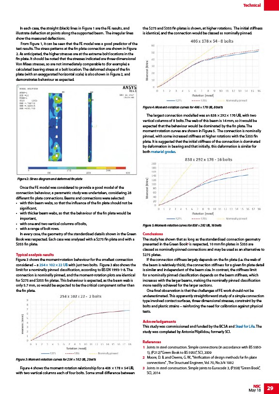
Figure 4 shows the moment-rotation relationship for a 406 × 178 × 54 UB,
with two vertical columns each of four bolts. Some small difference between
the S275 and S355 fin plates is shown, at higher rotations. The initial stiffness
is identical, and the connection would be classed as nominally pinned.
The largest connection modelled was an 838 × 292 × 176 UB, with two
vertical columns of 8 bolts. The web of this beam is 14 mm, so it would be
expected that the behaviour would be dominated by the fin plate. The
moment-rotation curves are shown in Figure 5. The connection is nominally
pinned, with some increased stiffness at higher rotations with the S355 fin
plate. It is suggested that the initial stiffness of the connection is dominated
by deformation in bearing and that initially, this deformation is similar for
both material grades.
Conclusions
The study has shown that as long as the standardised connection geometry
presented in the Green Book3 is respected, 10 mm fin plates in S355 are
classed as nominally pinned connections and may be used as an alternative to
S275 plates.
If the connection stiffness largely depends on the fin plate (i.e. the web of
the beam is relatively thick), the connection stiffness for a given fin plate detail
is similar and independent of the beam size. In contrast, the stiffness limit
for a nominally pinned classification depends on the beam stiffness, which
increases with the larger beams, making the nominally pinned classification
more readily achieved for the larger sections.
One final observation is that the challenges of FE work should not be
underestimated. This apparently straightforward study of a simple connection
type involved contact surfaces, three-dimensional stresses, constraint by the
bolts and plastic strains – reinforcing the need for calibration against physical
tests.
Acknowledgements
This study was commissioned and funded by the BCSA and Steel for Life. The
study was completed by Antonia Pilpilidou, formerly SCI.
References
1 Joints in steel construction. Simple connections (in accordance with BS 5950-
1), (P212) “Green Book to BS 5950”, SCI, 2009
2 Moore, D. B. and Owens, G. W., “Verification of design methods for fin plate
connections” , The Structural Engineer, Vol. 70, No.3/4 1992
3 Joints in steel construction. Simple joints to Eurocode 3, (P358) “Green Book”,
SCI, 2014
Figure 2: Stress diagram and deformed fin plate
Figure 3: Moment-rotation curves for 254 × 102 UB, 2 bolts
Figure 4: Moment-rotation curves for 406 × 178 UB, 8 bolts
Figure 5: Moment-rotation curves for 838 × 292 UB, 16 bolts
/Steel_section_sizes
/Steel_material_properties#Yield_strength
/Steel_for_Life