Distribution
Designing without expansion joints
Plot 520 is 349m long with no expansion joints. Richard Henderson of the SCI discusses the implications
20 NSC
May 18
accommodate ten full-size football pitches.
The portal-framed structure has six spans,
two at 37m and four at 31.5m.
To erect the frame Severfield used four
mobile cranes and a workforce of 25. The
erection method consisted of completing
one row of bays across the whole width of
the building before moving onto the next
set of bays.
Soon after each row was complete they
were handed over to the cladding team,
who worked immediately behind the steel
erectors. By working in this sequential
manner, the frame was weathertight soon
after the steel was completed.
The initial 200m-wide steelwork required
a significant amount of temporary bracing to
keep it stable during the erection process.
“Bearing in mind the structure is
20m-high and subject to quite considerable
wind loads, we had to design a temporary
bracing system for each of the span’s valley
lines,” explains Severfield Design Manager
Dan Dockerty.
Severfield used its own re-usable
temporary bracing system, which was
installed along with the main frame, and was
then removed once the permanent stability
system was installed.”
The building’s columns are 762 UBs along
the perimeters, while internally the company
has used plated columns. These members
support the roof rafters which were all
fabricated and delivered to site in two pieces
(two 18.5m rafters for the 37m span and two
15.75m sections for the other spans).
Once the main warehouse structure was
up, the final part of the steelwork package
involved the erection of an attached
three-storey office block. This building
required approximately 260t of steel and is a
Once 520 is complete
further distribution
centres are planned
traditional column and beam structure with
composite metal deck floors.
At ground floor, the 54m-long office
building bridges over a 16m-wide HGV
route into the warehouse. To create
this bridge, a series of plated girders
is positioned at first floor over the
thoroughfare.
Above the second floor level the building
also features a plant deck and an outdoor
terrace.
Plot 520 is scheduled for completion by
September.
18
Plot 520 comprises 3 bays of 9.66m and 40
bays of 8.0m between the centres of the
gable frames at the ends. A consideration
of the possibility of leaking expansion joints in
a portal frame with a clear height of 20 m and
the associated commercial risks, resulted in a
decision to design the building without joints.
Three vertical panels of tubular bracing provide
stability in the longitudinal direction and,
because the structure is continuous, the braced
panels inhibit free expansion due to temperature
changes. The design of the building includes
thermal load cases to take the thermal effects
into account where they arise in the continuous
members.
The internal temperature range recommended
in the Steelwork Design Guide to BS5950 Volume
4 Essential data for designers (SCI publication
P070) is -5 °C to +35 °C, a temperature range
of ΔT ± 20 K. The coefficient of linear thermal
expansion α = 12 × 10-6 K-1 so the maximum
thermal strain αΔT is about 2.4 × 10⁻⁴. Depending
on the position of the braced bays, expansion
joints could be required to allow for movement
of ± 40 mm; instead, the braced bays resist
expansion of the continuous members between
them, resulting in a maximum theoretical stress σ
= EαΔT of about 50 MPa which would arise if the
braced panels were perfectly rigid.
The building has six spans of portal frames
across the width of the building totalling 200 m.
The structural form of the portal frames means
that thermal expansion in the plane of the
frames results in an increase in the axial force in
the rafters, accompanied by a rise in the apex of
the frames. A reduction in temperature has the
opposite effect.
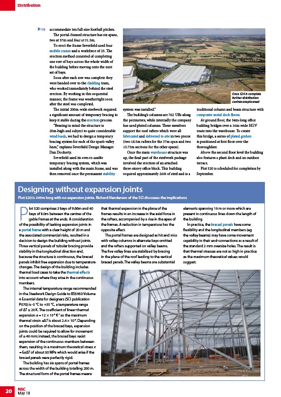
The portal frames are designed as hit and miss
with valley columns in alternate bays omitted
and the rafters supported on valley beams.
The five valley lines are stabilized by bracing
in the plane of the roof leading to the vertical
braced panels. The valley beams are substantial
elements spanning 16 m or more which are
present in continuous lines down the length of
the building.
In practice, the braced panels have some
flexibility and the longitudinal members (eg
the valley beams) may have some movement
capability in their end-connections as a result of
the standard 2 mm oversize holes. The result is
that thermal stresses are not as high in practice
as the maximum theoretical values would
suggest.
/Construction#Mobile_cranes
/Building_envelopes
/Construction#Steel_erection
/Design_codes_and_standards#Wind_actions
/Concept_design#Structural_options_for_stability
/Fabrication
/Fabrication#Handling_and_transportation
/Retail_buildings#Distribution_warehouses
/Floor_systems#Composite_slabs
/Steel_construction_products#Plate_girders
/Portal_frames
/Design_codes_and_standards#Thermal_actions
/Portal_frames#Vertical_bracing