Technical
NSC 29
April 19
Influence of the number of finite elements on frame stability:
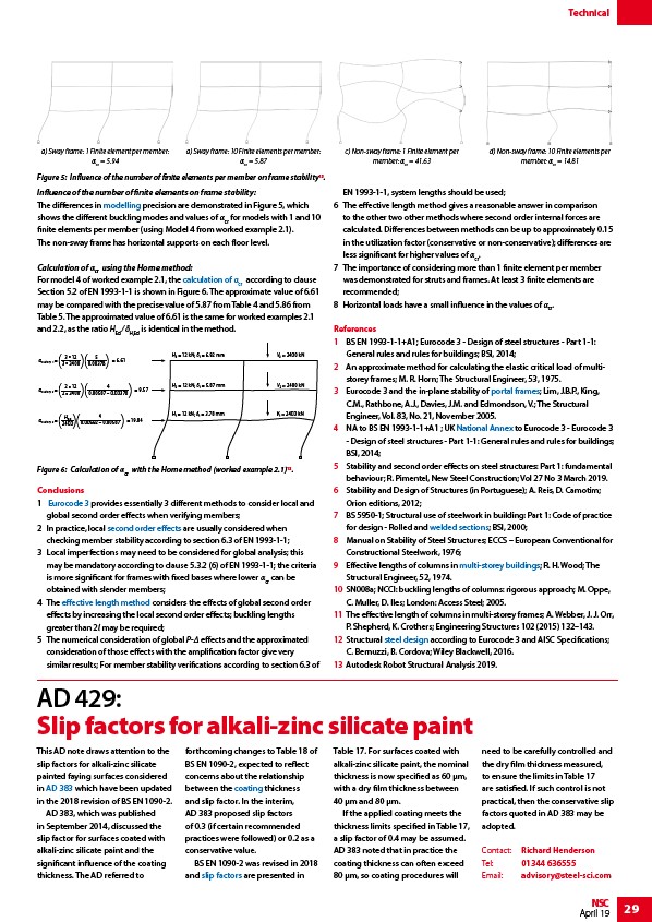
The differences in modelling precision are demonstrated in Figure 5, which
shows the different buckling modes and values of αcr for models with 1 and 10
finite elements per member (using Model 4 from worked example 2.1).
The non-sway frame has horizontal supports on each floor level.
Calculation of αcr using the Horne method:
For model 4 of worked example 2.1, the calculation of αcr according to clause
Section 5.2 of EN 1993-1-1 is shown in Figure 6. The approximate value of 6.61
may be compared with the precise value of 5.87 from Table 4 and 5.86 from
Table 5. The approximated value of 6.61 is the same for worked examples 2.1
and 2.2, as the ratio HEd ⁄ δH,Ed is identical in the method.
0.00378 ( )( )
0.00587 – 0.00378 ( )( )
0.00692 – 0.00587 ( )( )
Conclusions
1 Eurocode 3 provides essentially 3 different methods to consider local and
global second order effects when verifying members;
2 In practice, local second order effects are usually considered when
checking member stability according to section 6.3 of EN 1993-1-1;
3 Local imperfections may need to be considered for global analysis; this
may be mandatory according to clause 5.3.2 (6) of EN 1993-1-1; the criteria
is more significant for frames with fixed bases where lower αcr can be
obtained with slender members;
4 The effective length method considers the effects of global second order
effects by increasing the local second order effects; buckling lengths
greater than 2l may be required;
5 The numerical consideration of global P-Δ effects and the approximated
consideration of those effects with the amplification factor give very
similar results; For member stability verifications according to section 6.3 of
EN 1993-1-1, system lengths should be used;
6 The effective length method gives a reasonable answer in comparison
to the other two other methods where second order internal forces are
calculated. Differences between methods can be up to approximately 0.15
in the utilization factor (conservative or non-conservative); differences are
less significant for higher values of αcr.
7 The importance of considering more than 1 finite element per member
was demonstrated for struts and frames. At least 3 finite elements are
recommended;
8 Horizontal loads have a small influence in the values of αcr.
References
1 BS EN 1993-1-1+A1; Eurocode 3 - Design of steel structures - Part 1-1:
General rules and rules for buildings; BSI, 2014;
2 An approximate method for calculating the elastic critical load of multistorey
frames; M. R. Horn; The Structural Engineer, 53, 1975.
3 Eurocode 3 and the in-plane stability of portal frames; Lim, J.B.P., King,
C.M., Rathbone, A.J., Davies, J.M. and Edmondson, V.; The Structural
Engineer, Vol. 83, No. 21, November 2005.
4 NA to BS EN 1993-1-1+A1 ; UK National Annex to Eurocode 3 - Eurocode 3
- Design of steel structures - Part 1-1: General rules and rules for buildings;
BSI, 2014;
5 Stability and second order effects on steel structures: Part 1: fundamental
behaviour; R. Pimentel, New Steel Construction; Vol 27 No 3 March 2019.
6 Stability and Design of Structures (in Portuguese); A. Reis, D. Camotim;
Orion editions, 2012;
7 BS 5950-1; Structural use of steelwork in building: Part 1: Code of practice
for design - Rolled and welded sections; BSI, 2000;
8 Manual on Stability of Steel Structures; ECCS – European Conventional for
Constructional Steelwork, 1976;
9 Effective lengths of columns in multi-storey buildings; R. H. Wood; The
Structural Engineer, 52, 1974.
10 SN008a; NCCI: buckling lengths of columns: rigorous approach; M. Oppe,
C. Muller, D. Iles; London: Access Steel; 2005.
11 The effective length of columns in multi-storey frames; A. Webber, J. J. Orr,
P. Shepherd, K. Crothers; Engineering Structures 102 (2015) 132–143.
12 Structural steel design according to Eurocode 3 and AISC Specifications;
C. Bernuzzi, B. Cordova; Wiley Blackwell, 2016.
13 Autodesk Robot Structural Analysis 2019.
a) Sway frame: 1 Finite element per member:
αcr = 5.94
a) Sway frame: 10 Finite elements per member:
αcr = 5.87
c) Non-sway frame: 1 Finite element per
member: αcr = 41.63
d) Non-sway frame: 10 Finite elements per
member: αcr = 14.81
Figure 5: Influence of the number of finite elements per member on frame stability13.
cr,story 1 = 3 * 12
3 * 2400
= 6.61
5
cr,story 2 = 2 * 12
2 * 2400
= 9.57
4
cr,story 3 = HEd
2400
= 19.04
4
H = 12 kN; = 6.92 mm V 2400 kN
H = 12 kN; = 5.87 mm V 2400 kN
H = 12 kN; = 3.78 mm V 2400 kN
Figure 6: Calculation of αcr with the Horne method (worked example 2.1)13.
AD 429:
Slip factors for alkali-zinc silicate paint
This AD note draws attention to the
forthcoming changes to Table 18 of
Table 17. For surfaces coated with
slip factors for alkali-zinc silicate
BS EN 1090-2, expected to reflect
alkali-zinc silicate paint, the nominal
painted faying surfaces considered
concerns about the relationship
thickness is now specified as 60 μm,
in AD 383 which have been updated
between the coating thickness
with a dry film thickness between
in the 2018 revision of BS EN 1090-2.
and slip factor. In the interim,
40 μm and 80 μm.
AD 383, which was published
AD 383 proposed slip factors
If the applied coating meets the
in September 2014, discussed the
of 0.3 (if certain recommended
thickness limits specified in Table 17,
slip factor for surfaces coated with
practices were followed) or 0.2 as a
a slip factor of 0.4 may be assumed.
alkali-zinc silicate paint and the
conservative value.
AD 383 noted that in practice the
significant influence of the coating
BS EN 1090-2 was revised in 2018
coating thickness can often exceed
thickness. The AD referred to
and slip factors are presented in
80 μm, so coating procedures will
need to be carefully controlled and
the dry film thickness measured,
to ensure the limits in Table 17
are satisfied. If such control is not
practical, then the conservative slip
factors quoted in AD 383 may be
adopted.
Contact: Richard Henderson
Tel: 01344 636555
Email: advisory@steel-sci.com
/Modelling_and_analysis#Modelling
/Allowing_for_the_effects_of_deformed_frame_geometry#Calculation_of_.CE.B1cr
/Design_codes_and_standards#Eurocode_3_-_Steel_structures
/Allowing_for_the_effects_of_deformed_frame_geometry#Second_order_effects
/Allowing_for_the_effects_of_deformed_frame_geometry#Increased_buckling_lengths
/Portal_frames
/Design_codes_and_standards#National_Annexes
/Steel_construction_products#Plate_girders
/Multi-storey_office_buildings
/Design
/AD-383.pdf
/Paint_coatings
/Preloaded_bolting#Slip-resistant_connections
link