Technical
Members subject to combined
bending and compression
David Brown of the SCI reviews the options and available resources that can be used to
simplify the design checks and determine the required resistance data.
26 NSC
March 18
Expressions 6.61 and 6.62
These two expressions are well-known in the Eurocode steel
design world. They bring together a number of intermediate
calculations in a final crescendo of complexity, not helped by an
unfamiliar presentation of familiar terms. In fact, the expressions
are conceptually similar to the “more exact” approaches found
in BS 5950, containing an axial term, a major axis moment term
and a minor axis moment term. The denominators in the three
terms are the flexural buckling resistance, the lateral torsional
buckling resistance and the minor axis cross sectional resistances
respectively. The second two terms are modified by factors
that allow for the interaction between the different modes of
buckling.
If Class 4 sections are excluded the ΔM terms due to a shift
in the neutral axis can be removed, and if the denominators are
presented in more familiar terms, the two expressions become:
NMEd
+ ky,Ed
+ k 1 (6.61)
Nyy Myz
b,y,Rd
b,Rd
Mz,Ed
Mc,z,Rd
NEd
Nb,z,Rd
My,Ed
Mb,Rd
+ kzy 1 (6.62)
+ kzz
Mz,Ed
Mc,z,Rd
The main ratios are each
applied
resistance
. Purists should note that
the denominator in the final term is really
Wz fy
M1
, but this is
equal to the cross sectional resistance Mc,z,Rd since γM1 = γM0 = 1.0
The first task in using these expressions is to determine the
member resistances.
Member resistances from the Blue Book
The calculation of member resistances always starts from section
classification. The easy way to classify a section under combined
bending and axial load is to use the “n” limit given in the axial
force and bending tables of the Blue Book.
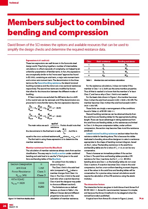
An extract from the tables is
shown in Figure 1.
The Class 2 limit is the axial load
ratio (compared to Npl,Rd) when a
member changes from Class 2 to
Class 3. The Class 3 limit is the axial
load ratio when a section becomes
Class 4 (and the designer may prefer
to choose a different section!).
The limitations are so defined
because, as shown in Table 1, the
different Classes demand different
properties to be used in the
calculation of member resistance.
Table 1: Member class and resistance calculations
For the resistance calculations, it does not matter if the
member is Class 1 or 2; both use the same member properties.
Thus all that is needed is to know that the member is “at least
Class 2”, and hence why a Class 1 limit is not needed.
For the beam data shown in Figure 1, the member becomes
Class 3 when the axial load exceeds 0.263 × 3620 = 952 kN. The
member becomes Class 4 when the axial load exceeds 0.839 ×
3620 = 3037 kN.
These limits are simply a rearrangement of the conditions
found in Table 5.2 of BS EN 1993-1-1.
Flexural buckling resistances can be obtained directly from
the axial force and bending tables for the appropriate buckling
length. There can be an advantage in taking resistances from
the axial force and bending tables, as the resistances are limited
to Class 3. In the pure compression tables, under uniform
compression, the section may become Class 4 and the resistance
penalised.
Lateral torsional buckling resistances are best taken from the
resistance table for bending alone. This is because the tables
dedicated to bending alone allow designers to select a resistance
appropriate to the shape of bending moment diagram, based
on the C1 value. The bending resistances in the axial force
and bending tables are for a value of C1 = 1.0, so can be very
conservative.
There is however an immediate problem if the section
is Class 3. The axial force and bending tables provide a LTB
resistance for Class 3 sections, but for C1 = 1.0. All UB in
bending alone are Class 1, so the bending tables do not cover
Class 3 sections. If a section becomes Class 3 due to the axial
compression, but has a non-uniform bending moment diagram,
use of the values in the axial force and bending tables will be
conservative. For a precise value, manual calculations would
require the calculation of the LTB resistance using the elastic
modulus.
The interaction factors
The interaction factors are given in both Annex A and Annex B of
BS EN 1993-1-1. Annex B is recommended, because it is simpler,
and because the Annex A method is to be relegated when the
revised Eurocode is published.
Figure 1:”n” limit from the Blue Book A typical term from Annex B is shown in Figure 2, (over).
28
Class Axial resistance Bending resistance
1 Ag Wpl
2 Ag Wpl
3 Ag Wel
4 Aeff Weff
/Member_design#Flexural_buckling_.28only.29
/Member_design#Classification_of_cross_sections
/The_Blue_Book
/Member_design#Lateral_torsional_buckling_resistance