Leisure
Redistributing loads The structure at Heron Quays is arranged to limit the loads applied to some
20 NSC
September 18
bracing system itself and on the most
critical piles. The bracing system was also
stiffened using welded plates to reduce the
sway deflections of the building.
Steelwork is based around an irregular
grid pattern, with columns spaced at 7m,
8m, 9m and 10m, in order to suit the pile
cap positions. One line of internal columns
allows the building to have uninterrupted
spans of up to 10m.
The upper floors are formed with steel
beams supporting a concrete slab on metal
decking. The slabs are generally 130mm
thick lightweight concrete and the steel
beams are generally 650mm-deep sections.
The steel beams are plated sections,
which are designed as 650mm-deep to fulfil
the deflection criteria and to allow services
to pass through the beams. Holes run
through the members on a regular grid to
allow the tenant maximum flexibility.
Erecting a building over water poses its
own challenges and during the steelwork
and metal decking installation the entire
footprint of the ground floor was decked
with floating pontoons to enable access for
workers and machinery.
“There were environmental challenges
and we had to seal the deck to prevent
grout loss into the dock, and while pouring
of concrete we had to monitor operations
from a boat to make sure there were no
substantial leaks,” adds Mr McDermott.
Steelwork contractor Elland Steel
Structures fabricated, supplied and installed
400t of weathering steel for the deck and
then a further 1,200t for the main structure.
“Most of the steelwork was installed
using the site’s 24t-capacity tower crane
which is situated alongside the dock
in a vacant plot,” sums up Elland Steel
Structures Contracts Manager Mark
Williamson.
“Although the deck and frame consists of
numerous heavy plate girders, none of the
steel was beyond the crane’s capacity.”
The project is scheduled for completion
in June 2019.
The structural arrangement of Heron
Quays Pavilion has been influenced by
the load carrying capacity of the existing
piles. The arrangement of the beams in the
transfer structure immediately above the
water has been chosen to allow redistribution
of loads in the event of settlement of certain
critical piles. By providing continuous beams
over these piles, any settlement will result in
load being redistributed to the adjacent piles,
thus relieving the load in the critical one. As
an example, consider a beam with two equal
spans continuous over its central support which
carries a uniform load. The actions in the beam
can be determined by equating the deflection
δB of the beam without the central support to
the deflection resulting from a central upward
point load. Settlement of the central support by
20% of the downward deflection δB of the beam
will result in 10% of the central support reaction
being transferred to each support at the outer
ends of the beam. It is likely that there is a high
tolerance on any prediction of pile settlement.
The magnitude of the load potentially
structural elements. Richard Henderson of the SCI discusses some of the details.
transferred to the outer supports can be
managed by adjusting the stiffness of the
beam such that the magnitude of the potential
settlement is a relatively small proportion of the
beam deflection δB.
The sequence of construction has been
modified to limit the permanent loads in the
bracing provided in the end elevations of the
building. To avoid openings in the façade, the
floor beams interrupt the bracing element
at first floor level and have a bracing node
near mid-span at levels three and four. As a
consequence, vertical loads applied to the
beams after completion of the bracing system
will result in axial loads in the bracing members.
To limit this effect, temporary bracing was
provided for stability during construction
and the bracing member connections were
detailed with preloaded bolts in slotted holes.
The beams were allowed to deflect under the
weight of concrete and the bracing joints were
completed after concreting had finished. The
loads in the permanent bracing resulting from
vertical loads on the floor beams were thereby
limited to the effects of permanent loads added
after completion of the floors (eg floor finishes,
services and ceilings) and of variable loads.
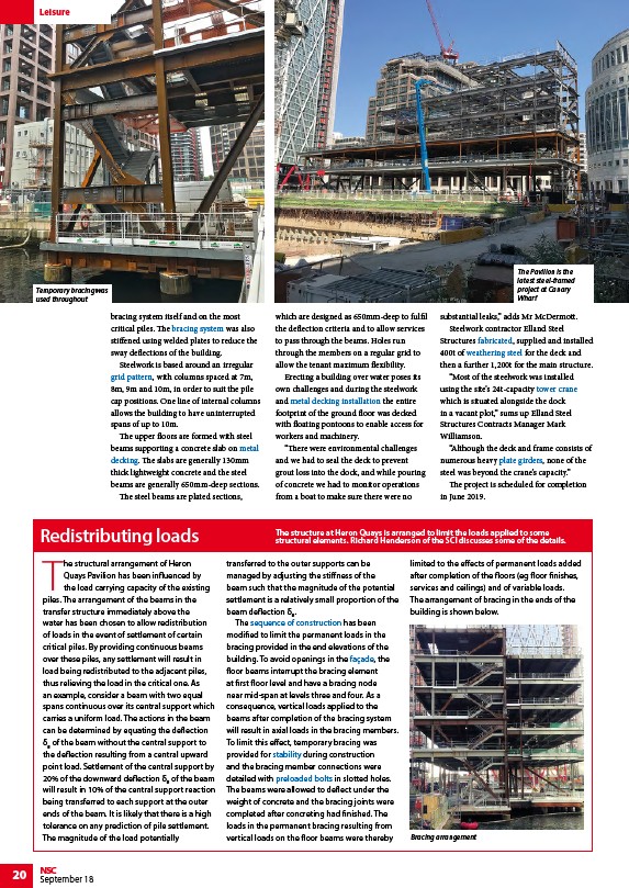
The arrangement of bracing in the ends of the
building is shown below.
Bracing arrangement
Temporary bracing was
used throughout
The Pavilion is the
latest steel-framed
project at Canary
Wharf
/Braced_frames#Vertical_bracing
/Concept_design#Floor_grids
/Steel_construction_products#Decking_for_floors
/Steel_construction_products#Decking_for_floors
/Construction#Installation_of_metal_decking
/Fabrication
/Weathering_steel
/Construction#Tower_cranes
/Steel_construction_products#Plate_girders
/Construction#Construction_sequence
/Facades_and_interfaces
/Concept_design#Structural_options_for_stability
/Preloaded_bolting