Technical
v
e
24 NSC
May 19
The design of crane girders
Recent correspondence in Verulam¹ suggested that there were no decent
examples of crane girder design to the Eurocodes. David Brown of the SCI rises to
the challenge…
The problem
According to the contribution in Verulam, a number of problems
exist with the design of a mono-symmetric member (a plate
welded to the top flange of a UB) and destabilising loads:
• BS 5950 examples have ‘mysteriously disappeared’ from the
equivalent Eurocode publications.
• The only way to design the member is to use ‘a piece of
software from a French website’.
• There is no way of checking the result (from the French
software).
• Gantry girders would have to be doubly symmetric, or have
the top flange fully restrained.
What are the options?
Looking back at the BS 5950 examples in the SCI library, most are
mono-symmetric with a channel welded to the top flange. An
example with a plain plate welded to the top flange is presented
in early editions of the ‘Red Book’2.
Some of the examples calculate the section properties of
the compound section – not a precise task, (especially before
channels had parallel flanges) and verify the fabricated member
on that basis. Alternative examples adopt the traditional and
simpler approach of assuming that the additional plate (or
channel) carries the horizontal loads, and the rolled section
carries the vertical loads.
If one held the pessimistic expectation that the Eurocodes
always adopt the most complex approach,
one might be pleasantly surprised to find
that the simple approach is allowed in
clause 5.6.2(4) of EN 1993-6, which is the
Standard covering the design of crane
supporting structures. According to this
clause, lateral loads are resisted by the top
flange, and vertical loads are resisted by
the main beam under the rail. This simple
approach will be familiar, and facilitates the
use of mono-symmetric sections.
Following this simple approach, torsional
moments are resisted by a couple acting
horizontally on the top and bottom flange.
As an alternative, torsion may be treated
rigorously.
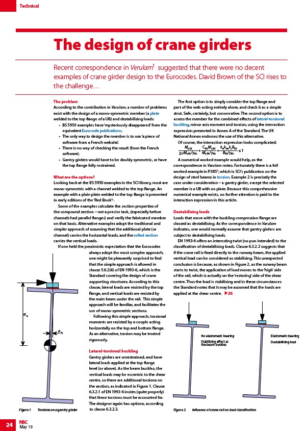
Lateral-torsional buckling
Gantry girders are unrestrained, and have
lateral loads applied at the top flange
level (or above). As the beam buckles, the
vertical loads may be eccentric to the shear
centre, so there are additional torsions on
the section, as indicated in Figure 1. Clause
6.3.2.1 of EN 1993-6 insists (quite properly)
that these torsions must be accounted for.
The designer again has options, according
to clause 6.3.2.3.
The first option is to simply consider the top flange and
part of the web acting entirely alone, and check it as a simple
strut. Safe, certainly, but conservative. The second option is to
assess the member for the combined effects of lateral-torsional
buckling, minor axis moment and torsion, using the interaction
expression presented in Annex A of the Standard. The UK
National Annex endorses the use of this alternative.
Of course, the interaction expression looks complicated:
My,Ed
LTMy,Rk/M1
CMzMz,Ed
Mz,Rk/M1
+ 1
+
kwkzwkBEd
BRk/M1
A numerical worked example would help, as the
correspondence in Verulam notes. Fortunately there is a full
worked example in P3853, which is SCI’s publication on the
design of steel beams in torsion. Example 2 is precisely the
case under consideration – a gantry girder, except the selected
member is a UB with no plate. Because this comprehensive
numerical example exists, no further attention is paid to the
interaction expression in this article.
Destabilising loads
Loads that move with the buckling compression flange are
classed as destabilising. As the correspondence in Verulam
indicates, one would normally assume that gantry girders are
subject to destabilising loads.
EN 1993-6 offers an interesting twist (no pun intended) to the
classification of destabilising loads. Clause 6.3.2.2 suggests that
if the crane rail is fixed directly to the runway beam, the applied
vertical load can be considered as stabilising. This unexpected
conclusion is because, as shown in Figure 2, as the runway beam
starts to twist, the application of load moves to the ‘high’ side
of the rail, which is actually on the ‘restoring’ side of the shear
centre. Thus the load is stabilising and in these circumstances
the Standard notes that it may be assumed that the loads are
applied at the shear centre.
26
e
h
Figure 1 Torsions on a gantry girder
No elastomeric bearing
Stabilising eect as
the beam buckles
Elastomeric bearing
Destabilising load
Figure 2 Influence of crane rail on load classification
/Steel_construction_products#Flat_products_-_plates
/Eurocode_Design_Guides
/Steel_construction_products#Standard_open_sections
/Member_design#Lateral_torsional_buckling_resistance
/Member_design#Lateral_torsional_buckling_resistance
/Member_design#Torsion