Technical
In Method 3, the designer must determine an appropriate effective length
that allows for the consideration of P-Δ effects while performing member
checks according to section 6.3 of EN 1993-1-1. As the design is based on
first order internal forces, the complexity of the analysis is removed, but
the effective length needs to be specified for each column. The concept of
effective length was introduced in Part 1 of the current article for isolated
struts, where the horizontal or rotational restraints of the strut ends were
assumed as infinitely rigid. This does not represent reality: (i) rotational
stiffness of the nodes is related to the flexural stiffness of the elements that
are connected to the nodes, resulting in a rotational spring on each node –
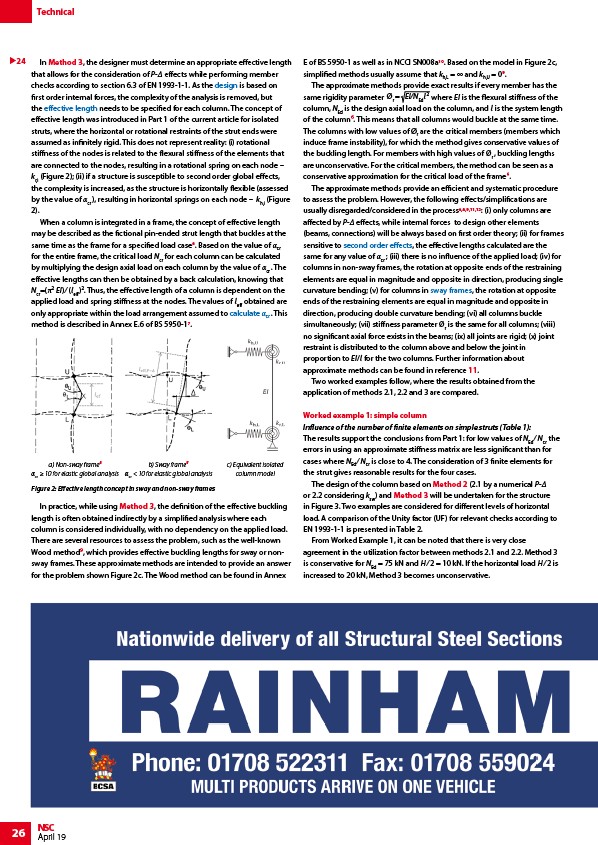
kr,i (Figure 2); (ii) if a structure is susceptible to second order global effects,
the complexity is increased, as the structure is horizontally flexible (assessed
by the value of αcr ), resulting in horizontal springs on each node – kh,i (Figure
2).
When a column is integrated in a frame, the concept of effective length
may be described as the fictional pin-ended strut length that buckles at the
same time as the frame for a specified load case6. Based on the value of αcr
for the entire frame, the critical load Ncr for each column can be calculated
by multiplying the design axial load on each column by the value of αcr . The
effective lengths can then be obtained by a back calculation, knowing that
Ncr=(π2 EI) ⁄ (leff)2. Thus, the effective length of a column is dependent on the
applied load and spring stiffness at the nodes. The values of leff obtained are
only appropriate within the load arrangement assumed to calculate αcr . This
method is described in Annex E.6 of BS 5950-17.
b) Sway frame8
αcr < 10 for elastic global analysis
In practice, while using Method 3, the definition of the effective buckling
length is often obtained indirectly by a simplified analysis where each
column is considered individually, with no dependency on the applied load.
There are several resources to assess the problem, such as the well-known
Wood method⁹, which provides effective buckling lengths for sway or nonsway
frames. These approximate methods are intended to provide an answer
for the problem shown Figure 2c. The Wood method can be found in Annex
26 NSC
April 19
E of BS 5950-1 as well as in NCCI SN008a10. Based on the model in Figure 2c,
simplified methods usually assume that kh,L = ∞ and kh,U = 09.
The approximate methods provide exact results if every member has the
same rigidity parameter Ør = EI/NEdl where EI is the flexural stiffness of the
column, NEd is the design axial load on the column, and l is the system length
of the column⁶. This means that all columns would buckle at the same time.
The columns with low values of Ør are the critical members (members which
induce frame instability), for which the method gives conservative values of
the buckling length. For members with high values of Ør , buckling lengths
are unconservative. For the critical members, the method can be seen as a
conservative approximation for the critical load of the frame⁶.
The approximate methods provide an efficient and systematic procedure
to assess the problem. However, the following effects/simplifications are
usually disregarded/considered in the process6,8,9,11,12: (i) only columns are
affected by P-Δ effects, while internal forces to design other elements
(beams, connections) will be always based on first order theory; (ii) for frames
sensitive to second order effects, the effective lengths calculated are the
same for any value of αcr ; (iii) there is no influence of the applied load; (iv) for
columns in non-sway frames, the rotation at opposite ends of the restraining
elements are equal in magnitude and opposite in direction, producing single
curvature bending; (v) for columns in sway frames, the rotation at opposite
ends of the restraining elements are equal in magnitude and opposite in
direction, producing double curvature bending; (vi) all columns buckle
simultaneously; (vii) stiffness parameter Ør is the same for all columns; (viii)
no significant axial force exists in the beams; (ix) all joints are rigid; (x) joint
restraint is distributed to the column above and below the joint in
proportion to EI/l for the two columns. Further information about
approximate methods can be found in reference 11.
Two worked examples follow, where the results obtained from the
application of methods 2.1, 2.2 and 3 are compared.
Worked example 1: simple column
Influence of the number of finite elements on simple struts (Table 1):
The results support the conclusions from Part 1: for low values of NEd ⁄ Ncr the
errors in using an approximate stiffness matrix are less significant than for
cases where NEd ⁄ Ncr is close to 4. The consideration of 3 finite elements for
the strut gives reasonable results for the four cases.
The design of the column based on Method 2 (2.1 by a numerical P-Δ
or 2.2 considering ksw) and Method 3 will be undertaken for the structure
in Figure 3. Two examples are considered for different levels of horizontal
load. A comparison of the Unity factor (UF) for relevant checks according to
EN 1993-1-1 is presented in Table 2.
From Worked Example 1, it can be noted that there is very close
agreement in the utilization factor between methods 2.1 and 2.2. Method 3
is conservative for NEd = 75 kN and H ⁄ 2 = 10 kN. If the horizontal load H ⁄ 2 is
increased to 20 kN, Method 3 becomes unconservative.
a) Non-sway frame8
αcr ≥ 10 for elastic global analysis
24
Figure 2: Effective length concept in sway and non-sway frames
c) Equivalent isolated
column model
/Design
/Allowing_for_the_effects_of_deformed_frame_geometry#Increased_buckling_lengths
/Allowing_for_the_effects_of_deformed_frame_geometry#Calculation_of_.CE.B1cr
/Allowing_for_the_effects_of_deformed_frame_geometry#Second_order_effects
/Continuous_frames