AD 415:
Vertical tying of columns and column splices
For compliance with the tying method of
providing robustness, vertical and horizontal ties
are required for buildings in Consequence Class
2B.
In the accidental action situation, vertical and
horizontal tying is required to redistribute loads
through the structure via alternative load paths,
away from locally damaged areas. This principle
is shown in Figure 1. Vertical ties also help to limit
the risk of the upper floor being blown upwards in
an explosion.
Figure 1
The differences in vertical tying requirements
of BS EN 1991-1-7(1) and BS 5950-1(2) has prompted
some questions. This AD note reviews those
differences and provides recommendations for
the design of vertical ties in accordance with BS
EN 1991-1-7.
BS EN 1991-1-7, clause A.6 (2) states: “The
column should be capable of resisting an
accidental design tensile force equal to the largest
design vertical permanent and variable load
reaction applied to the column from any one
storey”.
BS 5950-1, clause 2.4.5.3 (c) states: “All column
splices should be capable of resisting a tensile
30 NSC
February 18
resulting from any one storey.
If loads applied at one storey are very large,
possibly because (for example) transfer trusses
are supported at that level (see figure 9.2 in
P391), the accidental force to be accommodated
may dominate the selection of the column (and
splice connections) at upper levels. If this is the
case, it may be more advantageous to consider
the support to the transfer trusses to be a key
element, and design against its removal.
Contact: Andrew Way
Tel: 01344 636555
Email: advisory@steel-sci.com
(1) BS EN 1991-1-7:2006+A1:2014
Eurocode 1. Actions on structures. General
actions. Accidental actions
(2) BS 5950-1:2000 (BSI 2008) Structural use of
steelwork in building. Code of practice for
design. Rolled and welded sections
(3) BS 8110-1:1997 Structural use of concrete.
Code of practice for design and construction.
Amended by AMD 9882, AMD 13468.
Amendment, August 2007; Amendment,
November 2005
(4) BS EN 1990:2002+A1:2005 Eurocode. Basis of
structural design
(5) Structural robustness of steel framed buildings
(P391). SCI, 2011
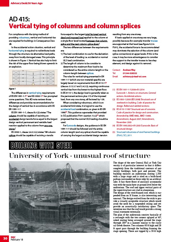
The shape of the new Central Hall at York University
is of particular interest in that it differs
completely from the traditional contours of university
buildings, both past and present. The
building encloses an auditorium seating 1,300
with a large stage and is sited on a brick-faced
podium surrounded on three sides by an artificial
lake. It has three floors of ancillary accommodation
with the main foyer at ground level below the
auditorium. The roof and upper vertical parts of
the superstructure are clad in aluminium.
The design of the steel-framed roof, which is suspended
from an ‘A’ frame, is also interesting and
unusual. The design evolved from the wish to provide
a visually acceptable structure which would
avoid the need for a suspended ceiling and yet
provide an acoustically satisfactory space. The
intention was that the roof would provide a strong
visual statement externally.
The plan of the auditorium consists basically of
a rectangle with the two corners splayed at 45°,
raked seating being arranged around the stage
through 180° in a manner similar to the classical
Greek theatre. Two columns 60 ft high and 28
ft apart pass through the building framing the
stage opening. These are topped by a 30-ft high
Advisory Desk/50 Years Ago
force equal to the largest total factored vertical
dead and imposed load applied to the column at
a single floor level located between that column
splice and the next column splice down”.
The two differences between the requirements
are:
1) The load combination to use for the derivation
of the level of loading i.e. accidental or normal
ULS load combination.
2) The length of column to be consider to
determine the maximum floor load to be
considered i.e. the entire column length or the
column length between splices.
The rules for vertical tying presented in EN
1991-1-7 (which are non-material specific) are
largely based on requirements from BS 8110-1(3)
(clauses 3.12.3.7 and 2.4.3.2), requiring continuous
vertical ties from the lowest to the highest floor.
In BS 8110-1, the design load is generally taken as
the permanent actions plus 1/3 of the imposed
load, from any one storey, all factored by 1.05.
When considering robustness, which is an
accidental limit state, it is logical to use the
accidental load combination, as given in BS EN
1990(4). This guidance supersedes that provided
in SCI publication P391 (section 7.3.2)(5) which
proposed that the normal ULS loading should be
used.
For Eurocode designs, the guidance in BS EN
1991-1-7 should be followed and the entire
column length (and any splice) should be capable
of carrying the largest accidental design tension
University of York - unusual roof structure
/Structural_robustness
/Structural_robustness#Horizontal_tying
/Structural_robustness#Vertical_ties
/Simple_connections#Column_splices
/Design_codes_and_standards#Accidental_actions
/Design_codes_and_standards#Introduction_to_Eurocodes
/Trusses
/Structural_robustness#Resources
/Structural_robustness#Resources
link