Technical
700.0
650.0
600.0
550.0
500.0
450.0
400.0
26 NSC
0.6 0.7 0.8 0.9 1 1.1
May 20
parameters are the rotational stiffnesses in kNm/radian at ends A
and B of the column of length h m and the deflection is in metres.
This deflection is added to the deflection due to element flexure
already calculated. The foot of the column is pinned so the
rotational stiffness at this end is zero. Substituting the values
H = 100 kN and h = 15 m gives δ = 0.113 m and a total lateral
deflection of 0.620 m. The revised global stiffness of the frame is
161 kN/m and the elastic critical load factor reduces to 8.07 -
second-order effects must therefore be considered.
The effect of the joint stiffness on the moments and
deflections due to vertical loads can be calculated by considering
rotations at the joint. The slope in the rafter is equal to the
simply-supported value reduced by the slope due to the end
moment. This rotation is equal to the slope in the column plus
the rotation due to the flexibility of the joint.
–
wL2
24EIb
ML
2EIb
=
Mh
3EIc
–
M
k
The value of M is 657.4 kNm, a reduction of 53.7 kNm. The midspan
moment increases to 467.5 kNm and the mid-span
deflection to 0.244 m.
The results can be confirmed by FE analysis, assuming
elements have infinite shear stiffness.
2.5 Effect of connection design resistance
According to BS EN 1993-1-8 para. 6.3.1, the rotational stiffness of
a beam-to-column joint Sj,ini is reduced by a factor μ that depends
on the joint utilization. If the design resistance is at least 1.5 times
the design bending moment, the initial stiffness of the joint can
be used in the analysis and μ = 1.0. If the resistance ratio is less
than 1.5 times, plastic deformation is assumed and a reduced
stiffness must be used.
μ = (1.5Mj,Ed / Mj,Rd)ψ where ψ = 2.7 for a bolted end plate.
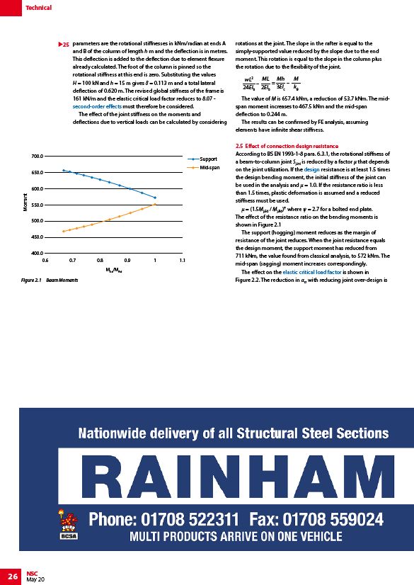
The effect of the resistance ratio on the bending moments is
shown in Figure 2.1
The support (hogging) moment reduces as the margin of
resistance of the joint reduces. When the joint resistance equals
the design moment, the support moment has reduced from
711 kNm, the value found from classical analysis, to 572 kNm. The
mid-span (sagging) moment increases correspondingly.
The effect on the elastic critical load factor is shown in
Figure 2.2. The reduction in αcr with reducing joint over-design is
25
Figure 2.1 Beam Moments
MEd/MRd
Moment
Support
Mid-span
/Portal_frames#Second_order_effects
/Design
/Portal_frames#Calculation_of_.CE.B1cr