Education
24 NSC
May 20
top of the tree system within the third-floor
slab.
“The tension forces are resolved through
a system of Macalloy high tension bars
within the concrete floor,” adds Mr Pang.
“Pre-tensioning the Macalloy bars during
construction allows pre-compression of the
floor slab, which reduces the risk of cracking
in the floor slab during normal loading
as the arms tend to splay apart under the
building loading.”
“Lifting the tree steelwork into position
and achieving the critical erection tolerances
was a difficult task,” says Bourne Steel Project
Manager Theo Pitrakkos. “The installation
programme was very tight, the pit lane for
offloading the steel has limited space and
the site logistics simply did not allow for
any storage. This meant that our deliveries
and lifting operations had to be planned so
the steel could be installed directly off the
transport vehicle with minimal handling.”
High strength steel of grade S460NL was
specified for the trees. This material had a
long lead time, was a challenge to source
within the programme constraints, and also
required original welding procedures to be
developed to suit the design requirements.
Bourne Steel Construction Manager, Steve
Condon adds: “To safely erect the complex
steelwork trees, we worked closely with the
temporary works design team to strategically
locate any lifting brackets, while also
reviewing the connection details to ensure
that the steel was erected within tolerance.
“We also trial erected both of the trees
at our Poole fabrication yard, prior to
delivering them to site, in order to make sure
they could be assembled correctly.”
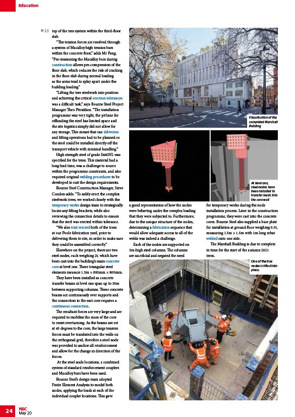
Elsewhere on the project, there are two
steel nodes, each weighing 2t, which have
been cast into the building’s main concrete
core at level one. These triangular steel
elements measure 1.5m × 800mm × 800mm.
They have been installed as concrete
transfer beams at level one span up to 30m
between supporting columns. These concrete
beams act continuously over supports and
the connection to the east core requires a
continuous connection.
The resultant forces are very large and are
required to mobilise the mass of the core
to resist overturning. As the beams are set
at 45 degrees to the core, the large tension
forces must be translated into the walls on
the orthogonal grid, therefore a steel node
was provided to anchor all reinforcement
and allow for the change in direction of the
forces.
At the steel node locations, a combined
system of standard reinforcement couplers
and Macalloy bars have been used.
Bourne Steel’s design team adopted
Finite Element Analysis to model both
nodes, applying the loads at each of the
individual coupler locations. This gave
a good representation of how the nodes
were behaving under the complex loading
that they were subjected to. Furthermore,
due to the unique structure of the nodes,
determining a fabrication sequence that
would allow adequate access to all of the
welds was indeed a challenge.
Each of the nodes are supported on
3m-high steel columns. The columns
are sacrificial and negated the need
Visualisation of the
completed Marshall
Building
At level one,
steel nodes have
been installed to
transfer loads into
the core wall
for temporary works during the node
installation process. Later in the construction
programme, they were cast into the concrete
cores. Bourne Steel also supplied a base plate
for installation at ground floor weighing 0.5t,
measuring 1.5m × 1.5m with 1m long rebar
welded onto one side.
The Marshall Building is due to complete
in time for the start of the autumn 2021
term.
One of the tree
nodes is lifted into
place.
23
/Construction
/Construction#Tolerances
/Fabrication#Handling_and_transportation
/Welding#Weld_procedure_specifications
/Construction#Temporary_works
/Accuracy_of_steel_fabrication#Trial_erection
/Concept_design#Concrete_or_steel_cores
/Concept_design#Concrete_or_steel_cores
/Moment_resisting_connections
/Fabrication
/Welding