Technical
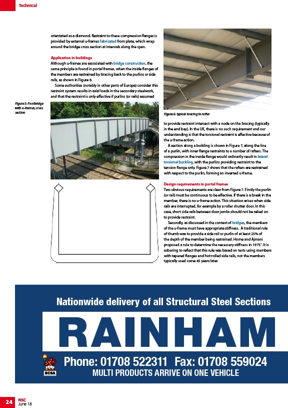
Figure 5: Footbridge
with u-frames; cross
section Figure 6: typical bracing to rafter
24 NSC
June 18
orientated as a diamond. Restraint to these compression flanges is
provided by external u-frames fabricated from plate, which wrap
around the bridge cross section at intervals along the span.
Application in buildings
Although u-frames are associated with bridge construction, the
same principle is found in portal frames, when the inside flanges of
the members are restrained by bracing back to the purlins or side
rails, as shown in Figure 6.
Some authorities (notably in other parts of Europe) consider this
restraint system results in axial loads in the secondary steelwork,
and that the restraint is only effective if purlins (or rails) assumed
to provide restraint intersect with a node on the bracing (typically
in the end bay). In the UK, there is no such requirement and our
understanding is that the torsional restraint is effective because of
the u-frame action.
A section along a building is shown in Figure 7, along the line
of a purlin, with inner flange restraints to a number of rafters. The
compression in the inside flange would ordinarily result in lateral
torsional buckling, with the purlins providing restraint to the
tension flange only. Figure 7 shows that the rafters are restrained
with respect to the purlin, forming an inverted u-frame.
Design requirements in portal frames
Two obvious requirements are clear from Figure 7. Firstly the purlin
(or rail) must be continuous to be effective. If there is a break in the
member, there is no u-frame action. This situation arises when side
rails are interrupted, for example by a roller shutter door. In this
case, short side rails between door jambs should not be relied on
to provide restraint.
Secondly, as discussed in the context of bridges, the members
of the u-frame must have appropriate stiffness. A traditional rule
of thumb was to provide a side rail or purlin of at least 25% of
the depth of the member being restrained. Horne and Ajmani
proposed a rule to determine the necessary stiffness in 19731. It is
sobering to reflect that this rule was based on tests using members
with tapered flanges and hot-rolled side rails, not the members
typically used some 45 years later.
Nationwide delivery of all Structural Steel Sections
RAINHAM Phone: 01708 522311 Fax: 01708 559024
MULTI PRODUCTS ARRIVE ON ONE VEHICLE
/Fabrication
/Design_for_steel_bridge_construction
/Member_design#Lateral_torsional_buckling_resistance
/Member_design#Lateral_torsional_buckling_resistance
/Bridges
/Fabrication
/Design_for_steel_bridge_construction
/Member_design#Lateral_torsional_buckling_resistance
/Member_design#Lateral_torsional_buckling_resistance
/Bridges