Projects and Features
Yin and yang towers
 Steelwork has been completed on the second of twin commercial buildings in King’s Cross, that have been designed to look like they have been pulled apart from each other.
FACT FILE
Building S1, King’s Cross, London
Main client: Argent
Architect: Mossessian & Partners
Main contractor: BAM Construction
Structural engineer: Ramboll
Steelwork contractor: Elland Steel Structures
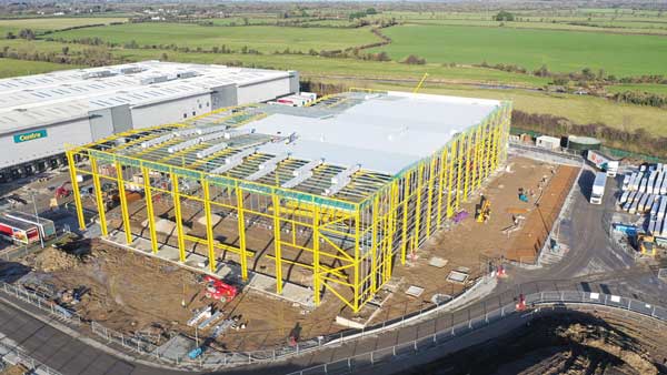
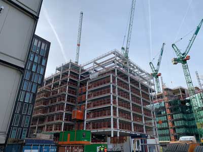
Steel tonnage: 2,400tForming the second building in a twin office development situated in the middle of Argent’s large King’s Cross scheme, S1 is a 12-storey structure offering more than 17,000m² of floor space.
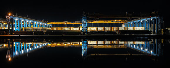
Along with its neighbour S2 (see NSC February 2018), which was completed last year, both buildings were conceived as a pair, sharing a number external features.
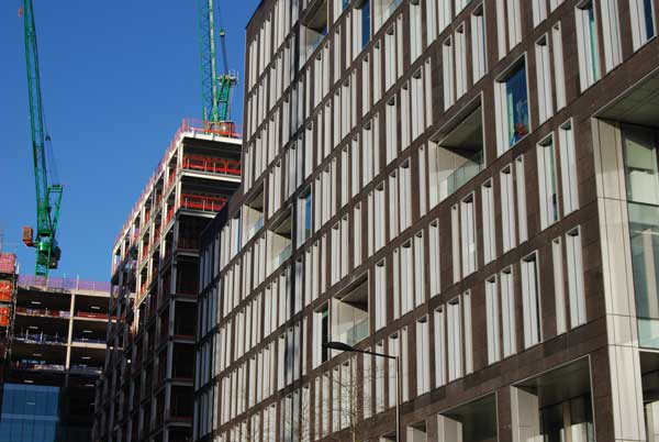
They both have the same façade finish, and this visual similarity means that when looking at the buildings from the eastern end of Handyside Street, the gap between the structures is not immediately visible, and the office blocks appear as one continuous development.
“King’s Cross is one of today’s templates for urban placemaking, so our priority, when asked to contribute two new buildings to this site, was to develop spaces that both convey a strong sense of their own identity and express a relevance to the public realm,” says Project Architect Michel Mossessian.
S1 and its neighbour S2 (on left) have been designed to look like one single entity
Both buildings have pop-out zones and recesses that make them look like they have been pulled apart
The atrium has been designed so that it can be infilled if required
“Sitting alongside each other along Handyside Street, Buildings S1 and S2 are linked stylistically: classically contemporary, they are clad in a textured black stone that frames them, forming the mass, while contrasting strongly with the light of white cavities of the façade.”
The two buildings have also been designed to look like they have been pulled apart from one larger mass. On each structure, the two facing facades have a series of cantilevering storey-high ‘pop-out’ zones and recesses. These are positioned in a reverse pattern to their neighbour and this yin and yang configuration gives the impression the buildings could also be pushed back together again.
According to Ramboll Director Simon Banfield, both buildings were originally designed as post-tensioned concrete structures, but they were changed to steel frames primarily because of cost and building weight.
On S1, structural steelwork’s flexibility and the ease with which last minute changes can be made during the fabrication process has come to the fore.
Working on behalf of BAM Construction, Elland Steel Structures completed the main steel frame for S1 in December 2019 on schedule, despite having to incorporate numerous design changes that totalled nearly 1,000t.
“The completed building has been let to two tenants, both of which requested changes to be made to the steel frame design,” explains BAM’s Construction Manager Justin Brown.
“They both wanted numerous staircase openings to be included to allow their floors to be linked, while the occupier of the lower six levels also wanted a fourth-floor atrium.”
All of the new openings, including the atrium have been formed with a reinstatement method, whereby design capacity, fixings and detailing have been provided ready for extra steel beams to be brought into the building, to simply infill the voids if the current tenants or new tenants in the future want an uninterrupted floorplate.
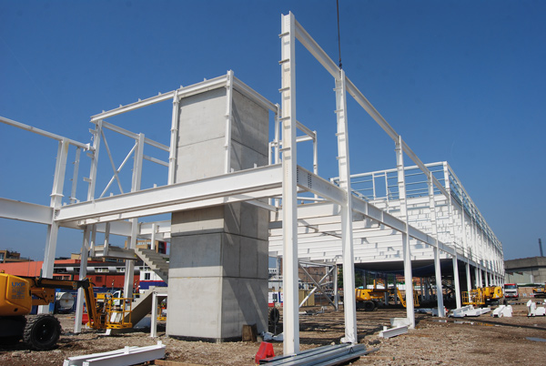
Prior to the steel frame being erected, the S1’s most challenging aspect, namely two Thameslink tunnels that run beneath the building, had to be bridged over with a large ground floor transfer structure.
This concrete structure not only transfers the building’s loads away from the tunnels, it also forms the structure’s basement level.
“Because of the tunnels, the project has had to be conducted with full agreement from Network Rail, while steelwork’s relative lightness compared to other framing materials was an important design choice on account of the underground rail assets,” says Mr Brown.
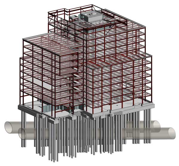
Model showing the main frame and the Thameslink tunnels that run beneath the site
The steel frame begins at ground floor and includes a double-height space for this lowest level. This floor accommodates the building’s main entrance alongside a number of retail outlets.
From first floor upwards the steel design is fairly regimented, based around a 9m column grid pattern, with internal spans up to 12m long.
One concrete core supplies the majority of structural stability to the steel frame, although as Mr Banfield explains, it was designed to be as small as possible in order to minimise the weight of the building over the railway tunnels.
“The core is also positioned slightly off centre and so structurally the building wants to twist. To prevent this and to supply extra stability, there are two 3m-wide braced bays that extend up the entire building.”
One of the exceptions to the regimented design is the fourth-floor atrium, which is positioned within one half of the building and extends upwards to the underside of level seven. A fifth-floor area wraps around the perimeter of the atrium and, because this floor area does not line up with the rest of the building’s column lines, it is hung from the floor above via a series of steel hangars.
In order to install this hanging floor, Elland Steel had to erect the level above and then wait until the composite flooring had been installed. Once this was done, the hanging fifth-floor level was installed with the use of temporary supports.
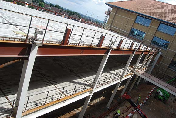
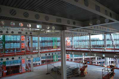
Aesthetics have played a key role in the steelwork design of S1 as the interior steelwork, as well as the underside of the soffit, will be left fully-exposed within the completed scheme. Cellular beams have been used throughout to accommodate the building’s services and these will also be on show.
Because of the exposed nature of the design, all of the cellular beam’s holes are the same diameter, in order to give a uniform appearance. In conjunction with this, careful consideration has been given to the appearance of all of the connections and the orientation of the bolts, while a basic specification of intumescent paint has been applied offsite to all of the columns and beams, then carefully touched-up on site to give a consistent appearance.
The desire to have uniformity and visual appeal within the steel frame has also extended to the perimeter columns. Every member is selected from the same family of Universal Column sections to appear the same size, unlike most other buildings were sections usually decrease in size the further up the structure they are.
Of the approximate 3,000 individual steel elements on Building S1, the largest is a 12m-long transfer structure, weighing 22t that facilitates a 6m setback in the building above this level and helps to form a 6m-wide, 39m long strip of terrace at the 7th floor level.
As a single piece this plate girder would have been too heavy for either of the site’s two tower cranes. Consequently, it was brought to site in two pieces and spliced together once the sections were in their final position.
Building S1 is due to be complete by February 2021.
 Connection Details
David Brown of the SCI comments on the connection details at Building S1, Kings Cross.
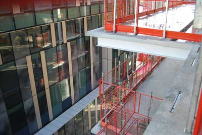
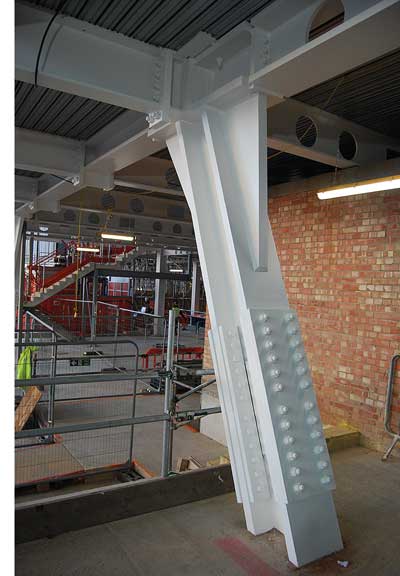
Like many large structures, Building S1 provides examples of commensurately large joints between members. Large splices with internal and external flange cover plates can be clearly seen together with reinforcement to dissipate load over a larger area at the upper joint.
The photo also shows cantilever supports to an upper floor. The cantilever moment is transferred through a supporting beam (which in this instance is shallower than the cantilever it supports) into a back span.
The common problem of introducing unwelcome torsion into the supporting beam has been managed by this careful arrangement. Open sections are notoriously poor at resisting torsion – large twists can result, so the arrangement at Building S1 is much preferred.
The moment connection between the cantilever and the supporting beam is often verified in software by modelling a column section as a vertical member and verifying the components within the joint in the normal way. The actual joint is then detailed by fabricating an equivalent section to the ‘column’ used in the software – identical or larger plates in place of the column flanges and webs – and welding this arrangement to the supporting beam. This same process is often used on the ‘miss’ frame of ‘hit and miss’ portals, where the rafters of the ‘miss’ frame must be supported by a valley beam. The connection is often based on precisely the same detailing as a ‘hit’ frame, but fabricated from plate or cut from a rolled section.
Although the modelling process has verified the bolts and plates, the welds to transfer the resulting forces to the supporting beam must be carefully considered. The weld sizes are likely to be identical to those between the cantilever beam and its end plate. The detail shown at Building S1 is interesting, because the bottom flange of the supporting beam is almost at the same level as the compression (lower) flange of the cantilever beam. Some engineering judgement would probably conclude that the bottom flange of the supporting beam is close enough to the compression flange and acts as a perfectly good compression stiffener.
The detail also shows the challenges sometimes faced by connection designers – in this example, the limited opportunities to locate the bolts within the shallower depth of the supporting beam.