Technical
Bolt slip in connections
The effect of bolt slip in truss connections is an issue that is raised with SCI from time to time
in various contexts. Richard Henderson discusses some of the issues.
24 NSC
Nov/Dec 19
Introduction
The deflection of a truss can be estimated using various analytical
methods and often a stick finite element (FE) package will be
used to determine the member forces and the deflections under
the different load cases. The calculated deflection depends on
the assumptions made in the analysis about the nature of the
joints – whether pinned or rigid.
Truss Joint types
In BS EN 1993-1-8, three categories of bolted connection loaded
in shear are identified:
• Category A: bearing connections where the bolts act in
shear and bearing;
Connections made with preloaded bolts:
• Category B: slip-resistant at serviceability limit state;
• Category C: slip-resistant at ultimate limit state.
Connections in category B must also be designed for shear
and bearing in the ultimate limit state and Category C for
bearing and net area. Fewer bolts will be required in Category B
connections than in Category C ones.
SCI recommends adopting joints made with preloaded bolts
where members are spliced and deflection is of concern because
this allows the deflection of a truss to be better controlled.
Category B joints are usually sufficient but Category C joints
maybe specified in special cases (eg with oversize or slotted
holes). In theory, once the joints are made, the subsequent
deflection of the structure is due only to the elastic deformation
of the members.
Predicting deflections in trusses
As discussed in the introduction, an FE model of a truss will
deliver the deflections of the structure as well as the member
forces for a given load case. The actual deflection of a truss
made with Category A bolted joints may well be greater than
the predicted deflection, because the joints may slip when the
load comes onto the structure and the bolts take up their loaded
position. The deflection will be more significant if holes are
oversize or slotted. This effect may be predicted by using virtual
work methods which assume a pin-jointed model and adding an
allowance for the slip at each bolted connection to the extension
of the member due to the internal forces. This can be illustrated
by example.
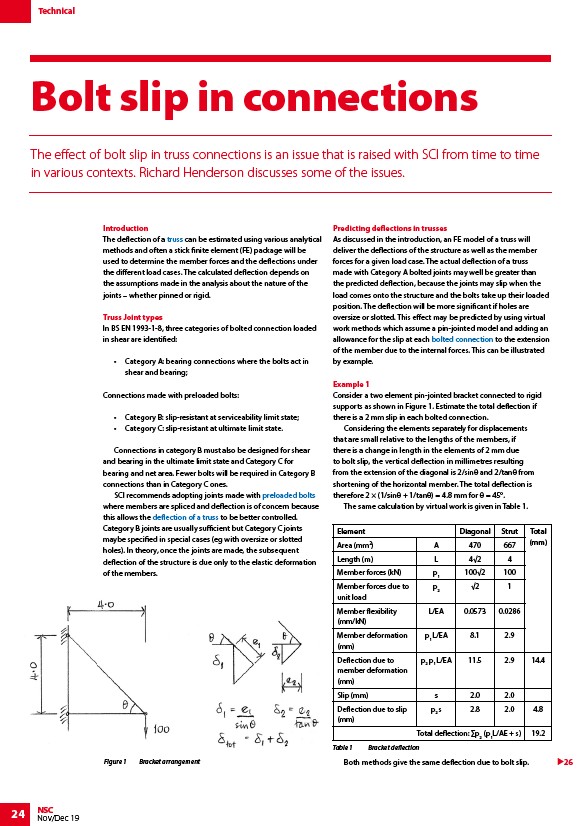
Example 1
Consider a two element pin-jointed bracket connected to rigid
supports as shown in Figure 1. Estimate the total deflection if
there is a 2 mm slip in each bolted connection.
Considering the elements separately for displacements
that are small relative to the lengths of the members, if
there is a change in length in the elements of 2 mm due
to bolt slip, the vertical deflection in millimetres resulting
from the extension of the diagonal is 2/sinθ and 2/tanθ from
shortening of the horizontal member. The total deflection is
therefore 2 × (1/sinθ + 1/tanθ) = 4.8 mm for θ = 45°.
The same calculation by virtual work is given in Table 1.
Element Diagonal Strut Total
Area (mm2) A 470 667 (mm)
Length (m) L 4√2 4
Member forces (kN) p100√2 100
1 Member forces due to
p√2 1
2 unit load
Member flexibility
(mm/kN)
L/EA 0.0573 0.0286
Member deformation
(mm)
p1 L/EA 8.1 2.9
Deflection due to
member deformation
(mm)
p2 p1 L/EA 11.5 2.9 14.4
Slip (mm) s 2.0 2.0
Deflection due to slip
(mm)
p2 s 2.8 2.0 4.8
Total deflection: Σp2 (p1L/AE + s) 19.2
Table 1 Bracket deflection
Figure 1 Bracket arrangement 26
Both methods give the same deflection due to bolt slip.
/Trusses
/Preloaded_bolting
/Trusses#The_effect_of_non-preloaded_assemblies_on_truss_deflection
/Trusses#Connections