Mixed-use
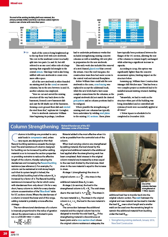
The roof of the existing building (left) was removed, the
atrium partially infilled and three new floors added (right) to
create a new scheme with more floor space
20 NSC
June 19
PLANT PLANT
OFFICE OFFICE
OFFICE
OFFICE
OFFICE
OFFICE
OFFICE OFFICE
Each of the cores is being heightened up
to the top floor level with new steelwork.
The core in the southeast corner is actually
split into two parts (1a and 1b, but still
referred to as one core) either side of a large
opening that originally led straight to the
central atrium. This large void is also being
infilled with new steelwork to create even
more office space.
All of the new steelwork is either founded
on existing steel (in the cores) or concrete
columns, but in the area between 1a and 1b,
another solution was employed.
“Here we cut and carved the existing
structure all the way back down to the
basement, formed a new basement slab
and cast the lift shafts out of the basement,
forming a new ground floor slab and erected
the steel from this,” explains Mr Carragher.
Prior to steelwork contractor William
Hare beginning its package, Lendlease
ROOF
08
07
06
05
04
03
02
01
PLANT PLANT
OFFICE
OFFICE
OFFICE
OFFICE
OFFICE OFFICE
OFFICE
OFFICE
had to undertake preliminary works that
included strengthening existing concrete
columns as well as installing 180 new piles
in preparation for the new steelwork.
This early work also included the removal
of a steel-framed glazed roof that covered
the atrium. Once the roof was gone, the
construction team then had easier access to
the central void and internal floorplates.
Before William Hare could add the new
steelwork to the cores, cross bracing was
replaced to accept the additional loads,
while the new levels had to have some
complex connections for the columns, as the
original steelwork did not match the desired
grid pattern and so column positions had to
be realigned.
Where possible the strengthening of
existing steel core columns has typically
been undertaken by welding steel plates
to the existing UC sections. These plates
OFFICE
have typically been positioned between the
flanges of the UC section, allowing the size
of the columns to remain largely unchanged
while achieving a significant increase in
capacity.
According to Arup, this option was
significantly lighter than the concrete
encasement option, limiting impact on the
structure below.
Summing up, William Hare Construction
Manager Bill Fletcher says: “This has been a
very complex project as steelwork had to be
installed around existing retained cladding
panels.
“Meanwhile, we had to work on the
structure when part of the building was
being demolished and so controlled safe
systems of work were successfully applied at
all times.”
1 Triton Square is scheduled to be
completed in December 2020.
ROOF
19
05
04
03
02
01
Columns in buildings are provided to carry
axial loads in compression and, unless
very squat, are designed so that their
flexural buckling resistance exceeds the design
load. The axial resistance of columns designed
for buckling can be increased by either adding
material so as to increase the section properties
or providing restraints to reduce the effective
length of the column, thereby reducing the
slenderness and increasing the flexural buckling
resistance (see reference i). For example, if a
column can be restrained at mid-storey height
such that its system length is halved, the
critical (Euler) buckling load of the column Ncr is
increased by a factor of 4. The flexural buckling
resistance is increased by a factor which varies
with slenderness from only about 13% for a very
short, heavy column to 340% for a very slender
column as examination of the “Blue Book” table
for UC sections shows. Where the slenderness of
a column is toward the lower end of this range,
adding material is probably a more effective
strategy.
The non-dimensional slenderness of a column
is inversely proportional to the radius of gyration
i about the relevant axis as indicated in para.
6.3.1.3 of BS EN 1993-1-1:2005:
=
Afy
Ncr
=
fy
E
L
1
i
Material added is the most effective when it is
as far as possible from the centroidal axis of the
column.
When load carrying columns are strengthened
by adding material, the load shared by the
original and additional material is the additional
load applied after the strengthening work has
been completed. Axial stresses in the original
column material are increased by a stress equal
to the new load divided by the total area. Axial
stress in the new material is equal to the increase
in stress.
At stage 1 (strengthening) the stress in
original column:
1 =
N1
A1
; the stress in the
additional material (Area A2 ) is zero.
At stage 2 (in service), the load in the
strengthened column is N1 + N2 . The axial stress
due to the new load is
2 =
N2
A1+A2
. The stress in
the new material is σ2. The stress in the original
column is σ1 + σ2 ; the load in the new material is
Nnew = A2 σ2.
The connection between the additional
material and the original column has to be
designed to transfer the axial load Nnew . If the
strengthening material is discontinuous at
beam joints and a cross section check shows
the original column resistance is adequate, the
additional load has to transfer back into the
original column section. The weld between the
original and new material can be sized to transfer
the load Nnew over a short length and a smaller
weld can be used over the remaining length to
restrain the additional material from buckling
under the load Nnew .
i: Strengthening existing steelwork, January 2019,
New Steel Construction
Column Strengthening Richard Henderson of the SCI
discusses some of the issues
GR
OFFICE
OFFICE
OFFICE OFFICE
RETAIL, GYM & AFFORDABLE WORKSPACE
PLANT
OFFICE
OFFICE OFFICE
GR
OFFICE
RETAIL, GYM & COMMUNITY USE
PLANT
OFFICE
One of the
columns that was
strengthened at
1 Triton Square
/Facades_and_interfaces#Steel_in_atria_and_canopies
/Concept_design#Concrete_or_steel_cores
/Construction#Steel_erection
/Steel-supported_glazed_facades_and_roofs#Atrium_Roofs_and_Sky_lights
/Braced_frames#Vertical_bracing
/Concept_design#Floor_grids
/Steel_construction_products#Flat_products_-_plates
/Steel_construction_products#Standard_open_sections
/Member_design#Compression
/Member_design#Flexural_buckling_.28only.29
/The_Blue_Book
/Member_design#Resistance_of_cross_sections
/Welding#Types_of_welded_connections