Shear and bending
The resistance of cross sections subject
to shear and bending – theoretical
analysis and practical design rules
Sections subject to both bending and shear have a reduced bending resistance where the
shear force is greater than half the shear resistance. Richard Henderson of the SCI discusses the
background and design rules.
Work carried out between 1930 and 1965 on the resistance of cross
sections capable of being designed plastically was presented by Baker,
Horne and Heyman1. Theoretical treatments of the effect of shear force on
the resistance moment of sections were developed and were subsequently
compared with tests. The design rules presented in BS 5950-1:2000 and
subsequently in BS EN 1993-1-1 were based on this work.
Horne2 examined rectangular and I sections and developed expressions
for the reduction in the bending resistance of cross sections where the
sections are subject to both bending and shear. In the examination, the
sections are assumed to be capable of carrying their full plastic moment:
sections are assumed to be restrained from global buckling and I sections
are either class 1 or class 2 according to EC3.
Rectangular Section
A rectangular section will carry a bending moment equal to its elastic
moment of resistance where only the extreme fibres reach yield stress.
The remainder of the cross section is able to resist a shear force. The shear
stress distribution is parabolic over the depth of the section and is zero at
the extreme fibres with a maximum value at the neutral axis. The average
shear stress is two thirds of the maximum value. If the bending moment is
increased above the elastic moment of resistance, the area of the section
available to resist shear is reduced until it vanishes when the plastic
moment of resistance is reached. At this point, the whole section reaches
its yield stress. The plastic resistance moment of the section is Mp = (bh2/4)fy
and its plastic shear resistance is Vy = bhτy if the bending and shear are each
considered on their own.
When the bending moment is between the elastic and plastic moment
of resistance, the elastic core of the section has a depth yo above and
below the neutral axis and yo < h/2 where h is the depth of the section. The
resistance moment is given by the sum of the plastic moment of resistance
of the outer portion and the elastic moment of resistance of the core:
M = b/4(h2 – 4yo
10 NSC
2)σy + 2/3byo
Technical Digest 2018
2σy
and the shear resistance is provided by the core and given by
V = 4/3byoτy.
Eliminating y0 and using the expressions for Mp and Vp gives:
Mpr/Mp = 1 – 3/4(V/Vp)2 (1)
Mpr is the reduced plastic moment of resistance in the presence
of shear. The expression is valid for values of V up to that for which
yo = h/2 ie V/Vp ≤ 2/3.
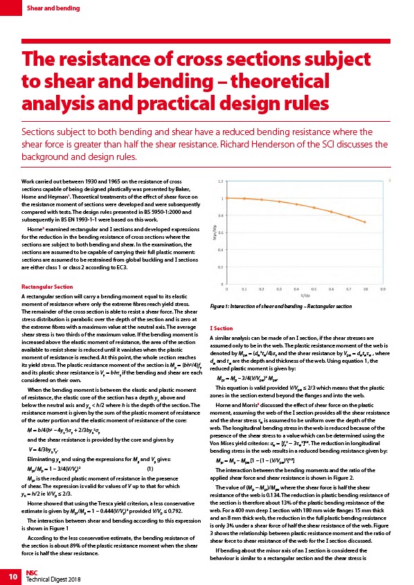
Horne showed that using the Tresca yield criterion, a less conservative
estimate is given by Mpr/Mp = 1 – 0.444(V/Vp)2 provided V/Vp ≤ 0.792.
The interaction between shear and bending according to this expression
is shown in Figure 1
According to the less conservative estimate, the bending resistance of
the section is about 89% of the plastic resistance moment when the shear
force is half the shear resistance.
Figure 1: Interaction of shear and bending – Rectangular section
I Section
A similar analysis can be made of an I section, if the shear stresses are
assumed only to be in the web. The plastic resistance moment of the web is
denoted by Mpw = (dw
2tw/4)σy and the shear resistance by Vpw = dwtwτw , where
dw and tw are the depth and thickness of the web. Using equation 1, the
reduced plastic moment is given by:
Mpr = Mp – 3/4(V/V)2 M.
pwpwThis equation is valid provided V/Vpw ≤ 2/3 which means that the plastic
zones in the section extend beyond the flanges and into the web.
Horne and Morris3 discussed the effect of shear force on the plastic
moment, assuming the web of the I section provides all the shear resistance
and the shear stress τw is assumed to be uniform over the depth of the
web. The longitudinal bending stress in the web is reduced because of the
presence of the shear stress to a value which can be determined using the
Von Mises yield criterion: σw = f2 − 3τ20.5. The reduction in longitudinal
y
w
bending stress in the web results in a reduced bending resistance given by:
Mpr = Mp – Mpw 1 – {1 – (V/Vpw)2}0.5
The interaction between the bending moments and the ratio of the
applied shear force and shear resistance is shown in Figure 2.
The value of (Mp − Mpr)/Mpw where the shear force is half the shear
resistance of the web is 0.134. The reduction in plastic bending resistance of
the section is therefore about 13% of the plastic bending resistance of the
web. For a 400 mm deep I section with 180 mm wide flanges 15 mm thick
and an 8 mm thick web, the reduction in the full plastic bending resistance
is only 3% under a shear force of half the shear resistance of the web. Figure
3 shows the relationship between plastic resistance moment and the ratio of
shear force to shear resistance of the web for the I section discussed.
If bending about the minor axis of an I section is considered the
behaviour is similar to a rectangular section and the shear stress is