Technical
The C factor deals with the shape of the bending moment
diagram, and is taken from Table B3 of the Standard.
NEd
Cmy (1 + 0.8 )
Nkyy = C(1 + (y – 0.2) ) Ed
my NyRk M1
yNRk M1
Figure 2: Typical interaction factor
Again, the presentation of these terms is not very attractive.
In particular, the term χyNRk/γM1 is unhelpful, as it is simply the
flexural resistance (in this case in the major axis), or Nb,y,Rd . The
expressions might more helpfully be presented in the form in
Figure 3.
NEd
y( Nkyy = C1 + ( – 0.2) ) C(1 + 0.8 Ed
) my Nmy Nb,y,Rd
b,y,Rd
Figure 3: Typical interaction factor, revised presentation
The Blue Book cannot help here, as the expression demands an
intermediate value, λy used as part of the calculation process, but
not given in the tables.
Two options are available for the designer wanting to follow
the full process – calculate the intermediate values needed, or
use the graphical presentation of these interaction factors given
in SCI Publication P3621.
Bringing it all together
Designers have options to use simplified versions of these two
expressions, with differing degrees of conservatism. An example
of each follows, and then finally a comparison with the full
expression. The comparisons are illustrated with a numerical
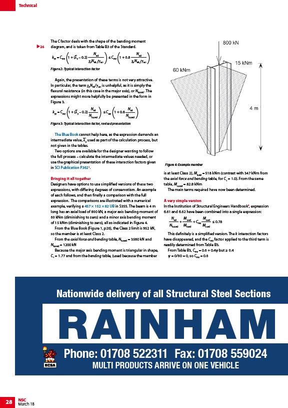
example, verifying a 457 × 152 × 82 UB in S355. The beam is 4 m
long has an axial load of 800 kN, a major axis bending moment of
60 kNm (diminishing to zero) and a minor axis bending moment
of 15 kNm (diminishing to zero), all as indicated in Figure 4.
From the Blue Book (Figure 1, p26), the Class 2 limit is 952 kN,
so the member is at least Class 2.
From the axial force and bending table, Nb,y,Rd = 3560 kN and
Nb,z,Rd = 1200 kN
Because the major axis bending moment is triangular in shape,
C1 = 1.77 and from the bending table, (used because the member
is at least Class 2), Mb,Rd = 518 kNm (contrast with 347 kNm from
the axial force and bending table, for C1 = 1.0). From the same
table, Mc,z,Rd = 82.8 kNm
The main terms required have now been determined.
A very simple version
In the Institution of Structural Engineers Handbook2, expression
6.61 and 6.62 have been combined into a single expression:
NEd
Nb,z,Rd
My,Ed
Mb,Rd
Mz,Ed
Mz,Rd
+ 0.78
+ Cmz
This definitely is a simplified version. The k interaction factors
have disappeared, and the Cmz factor applied to the third term is
readily determined from Table B3.
From Table B3, Cmz = 0.6 + 0.4ψ but ≥ 0.4
ψ = 0/60 = 0, so Cmz = 0.6
Figure 3: Tee dimensionsRAINHAM Nationwide 28 NSC
March 18
delivery of all Structural Steel Sections
Phone: 01708 522311 Fax: 01708 559024
MULTI PRODUCTS ARRIVE ON ONE VEHICLE
26
Figure 4: Example member
/The_Blue_Book
/Eurocode_Design_Guides
/Steel_section_sizes