Projects and Features
Trusses provide towering support
 The centrepiece of a central London mixed-use development is two residential towers supported on a series of 15 steel trusses.
FACT FILE
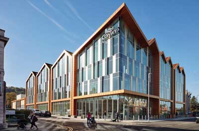
One Crown Place, London
Main client: AlloyMtd
Architect: Kohn Pedersen Fox
Main contractor: Mace
Structural engineer: AKT II
Steelwork contractor: Severfield
Steel tonnage: 2,600tA prestigious mixed-use scheme is set to invigorate a central London district with its blend of 246 residential apartments, 15,500m² of Grade A office space, and a boutique hotel and restaurant.
Known as One Crown Place, the scheme is close to both Liverpool Street and Moorgate stations, only metres outside of the City of London boundary and situated in the Borough of Hackney.
Its position on the fringes of both the square mile and the thriving Shoreditch district means the development will offer numerous amenities for office workers and residents alike.
Bounded on three sides by roads and the pedestrianised Crown Place on the fourth, the development occupies most of an island site, with the only exceptions being a retained chapel and pub, both of which have remained open throughout the works.
Along the site’s southern Sun Street boundary, a previously dilapidated Georgian terrace has been retained and is being converted into the development’s boutique hotel.
Emphasing the fact that the scheme is truly mixed-use in both use and architectural design, along the northern Earl Street elevation, a further Victorian façade is retained to be incorporated into the new build office scheme, while next to this a 1980s-office block, currently serving as a marketing suite and site offices, will be refurbished into a new stand-alone office block once the main project has completed.
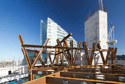
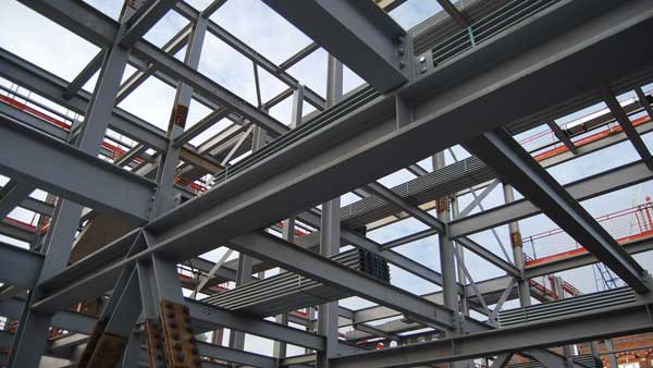
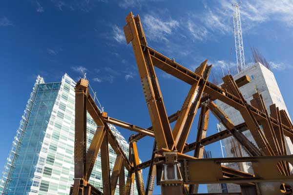
One of the 15 trusses during the erection programme
The trusses will form an architectural feature in the completed scheme
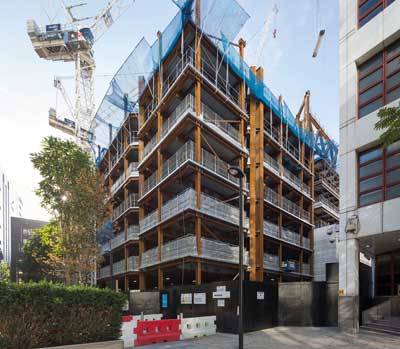
A six-storey steel podium is topped by the structurally-important trusses
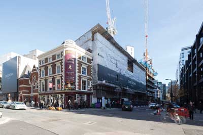
The overall project includes a number of retained elements including a pub and a Georgian façade (under wraps)
Alongside these disparate elements, the main part of the development is positioned at the eastern end of the site where a six-storey podium supports two apartment towers, that will reach heights of 33 and 29 levels respectively.
This part is reliant on structural steelwork as the podium is a steel-framed structure topped by a series of 15 trusses. These steel trusses have three functions. Firstly they help to create the clear column-free internal office spans of up to 12m for the floors up to level six.
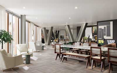
Secondly, levels seven and eight are accommodated within their depth, where the truss elements will be left exposed as architectural highlights.
Level 7 will accommodate a gym, a work hub, private screening room, meeting space and other exclusive amenities for the residents, while level 8 is given over to apartments.
And thirdly, and possibly most importantly, the trusses support the two-reinforced concrete (RC) residential towers that begin at level 9.
The change in construction materials at level 9 presented a challenge of transferring the smaller RC column grid of the towers to the larger steel structural grid below. This was resolved by using the trusses to support the change in the column grid pattern.
This is the transition zone between the steel and concrete parts of the scheme and it required a lot of coordination during the design phase between steelwork contractor Severfleld and the reinforced concrete contractor.
“There are a lot of steel-to-concrete interfaces, particularly along the top of the trusses where the tower’s columns will be sat. Here we’ve had to install stiffeners for the rebar, while on the underside of the trusses, at these column locations, we’ve added stiffened nodes, some of which are up to 150mm thick,” says Severfield Project Manager Richard Grey. “
There are 15 trusses in total of varying length, with the longest being 25m. There are eight double-height trusses, that accommodate two floor levels, and seven single level trusses.
Some of the single trusses are located where there is a set-back in the building accommodating a terrace, or in areas that will not need to absorb such heavy loadings as other zones. Above these slimmer trusses, a series of stub columns bring the steelwork up to level nine.
A variety of UC section sizes are used for the trusses with a number of them being 356 × 406 × 634 UC’s. In some areas, the diagonal bracing elements have been pulled apart (un-noded) to provide sufficient space for doorways.
“The result of this un-noding has resulted in a huge local shear load – V=10,620kN, equivalent to 84 double decker busses – in the top boom,” explains Mace Senior Project Manager Thomas Kercel.
“In these locations, in order to provide a member with adequate capacity the standard rolled UC has been replaced with a fabricated plate section. The webs of these fabricated sections are up to 150mm in thickness in order to provide the required shear capacity,” he adds.
The trusses are supported at either end by a series of 600mm squared and double-webbed mega-columns, each fabricated from four plate sections.
All of the podium’s columns are founded at ground level above a three-level deep basement. The subterranean level is predominantly formed with concrete, although some columns are steel members encased in reinforced concrete.
Based around a centrally positioned core, Fabsec cellular beams, accommodating all of the services, span outwards to the perimeter to form the desired column-free office spans.
The mega-sections account for approximately 50% of the podium’s columns and are spliced at every second floor. Like all of the project’s steelwork, the mega-columns had to be restricted to 9t sections so that each piece would fall within the lifting capacity of the site’s tower cranes.
“It’s a very confined project with no room for a mobile crane on site or on any of the surrounding streets, so everything has to be lifted by one of our three tower cranes,” explains Mr Kercel.
Keeping the trusses to manageable pieces meant each one was delivered to site in at least 11 sections. The erection process had to be carefully planned with close tower crane co-ordination required to erect the trusses. Individual elements were held in place with one tower crane, while another section was craned in and connected before each truss was stable.
To reduce crane lifts and the risk of additional bolting at height, the flange splice plates were profiled with rounded ends and bolted on prior to transit. This allowed them to be swung round to complete the splice connection at high level. The web splice plates were then bolted on to alternate sides to complete the jigsaw.
Prior to delivery, each of the trusses was trial erected at Severfield’s fabrication yard to ensure they could be fully assembled on site.
“This process also gave the client the opportunity to see the completed trusses,” says Mr Kercel. “It was also interesting for them to observe the assembled steelwork and the large splices as some will be left exposed in the completed scheme.”
One Crown Place is due to complete in February 2021.
 Non-slip splice joints
David Brown of the SCI comments on the trusses’ design
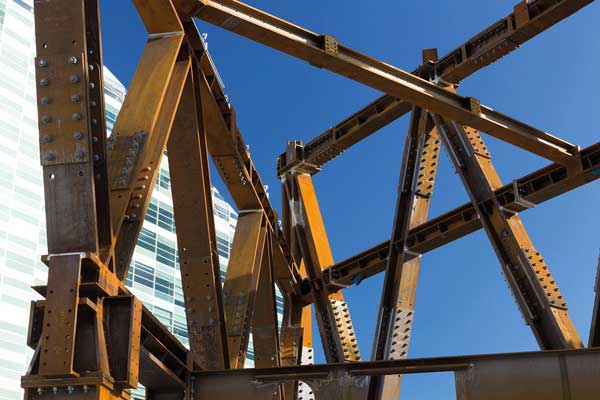
Substantial forces in the steel trusses at One Crown Place demand commensurate design and detailing of the splice connections – many of which can be seen in the accompanying photographs. The splices have been detailed with preloaded assemblies to ensure that the joints do not slip – essential in trusses of this nature where there are many splices and slip would have led to significantly increased deflection.
The splices are detailed with cover plates on the inside and outside of the flanges to accommodate the large forces (and bending moments, since the truss was analysed with continuity at the nodes). A common assumption is to distribute axial force in proportion to the cross section of the member, so a UC flange typically carries around 40% of the axial force.
The splices at One Crown Place were designed as bearing splices – direct transfer of compressive forces between the members. BS EN 1993-1-8 specifies minimum requirements for the splice components in clause 6.2.7.1 (13) and (14) – the choice for a bearing splice is highly recommended. The same clause specifies that the web connection must carry a proportion of the bending moment, even if it had been assumed that moment was carried entirely by the flanges. This requirement tends to lead to larger web connections than previous UK practice.
When multiple bolts are required in the direction of the force, clause 3.8 requires a reduction factor to be applied reflecting the non-uniform distribution of force between bolts. A joint is described as ‘long’ if the distance between end fasteners exceeds 15d (bolt diameter). This should be checked each side of a splice joint.
As can be seen in the photographs, the mating surfaces (called ‘faying’ surfaces) of the splices were left unpainted – vital if a reasonable coefficient of friction is to be achieved. Good practice is to agree the value of the slip coefficient to be assumed before starting connection design, and secondly to agree if the connection is category B or C – non-slip at SLS or ULS respectively. If category B connections are designed, the slip resistance is verified at SLS, but the bolt shear and bolt bearing are both verified at ULS to ensure that resistance at ULS is sufficient. Category B is a reasonable design choice as the applied loads should never exceed SLS – something has gone badly wrong if this happens.
At One Crown Place, HRC bolts (commonly known as ‘tension control bolts’) were used. Preload in the bolt is achieved when the splined end of the bolt shank shears off as the nut is tightened. Tightening torque is applied by contra-rotating sockets within the electric shear wrench. This type of preloaded assembly is widely used in the UK.