Projects and Features
Trusses accommodate complex design
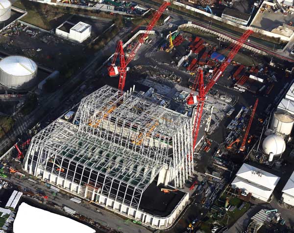
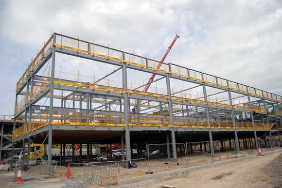
The large steel frame takes shape, with the tipping hall and waste bunker the first parts to be erected
Structural steel design innovations have played a key factor in the construction of Ireland’s largest waste to energy scheme. Martin Cooper reports.
FACT FILE
Dublin Waste to Energy project
Main client: Dublin City Council
Principal contractor: Covanta
Architect: Friis & Moltke Architects
Construction Manager: PM Group
Structural engineer: PM Group
Steelwork contractor: Severfield
Steel tonnage: 4,500tWe’ve pushed the boundaries of structural steel design, detailing and erection on this project,” says PM Group Senior Structural Engineer John Diffley, as he describes the work that has been undertaken to build the Dublin Waste to Energy facility.
“The unique geometry of the building posed significant technical design and construction challenges, such as working within a tight and confined site, which directly impacted the erection sequencing and logistics planning as well as working at height to lift large steel elements into place. All have all been overcome with a lot of design and construction coordination between PM Group and Severfield.”
The Republic of Ireland’s largest waste to energy plant is being constructed at Poolbeg in Dublin, close to where the River Liffey meets the Irish Sea. Once operational it will incinerate up to 600,000t of waste per year, generating enough electricity for up to 80,000 homes.
All of the project’s processes are housed within one large steel-framed structure that will minimise noise. It measures approximately 200m × 100m, rising to a maximum height of 52m (excluding the flue which will be 100m-tall).
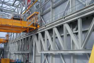
Three trusses support the waste bunker’s cranes
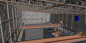
Design model of the bunker’s crane support steelwork
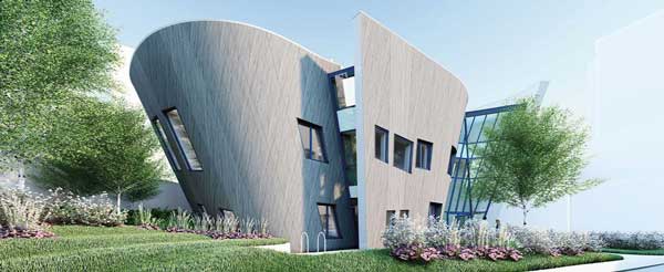
Because the structure is so large and will be a prominent feature of the local landscape, the design of the plant has created a landmark conical-shaped building. All of the corners are rounded, while the building also curves and slopes upwards creating complex steelwork geometry. This is predominantly formed with columns positioned around a radius and then connected with faceted steel tie members.
Such a challenging shape would not have been possible without the use of BIM, according to all of the design and steelwork team members. PM Group’s use of Revit and model management tool Navisworks and Severfield’s use of Tekla, led by their Technical Manager Stephen Graham, facilitated a detailed co-ordinated fabrication model that was clash-free with the extensive process and services models.
The building is divided into three frames by two movement joints along its length. The individual process areas are aligned with these joint locations. The initial construction phase included the waste bunker, the administration building, tipping hall and district heating areas.
Within the waste bunker structure two overhead waste handling gantry cranes will service the plant, operating 24 hours a day seven days a week.
“Usually overhead crane beams would be symmetrically supported by large evenly spaced columns on either side. However, due to the layout requirements of the processing equipment, a space adjacent to the bunker needed to be open-plan and so columns could not be placed on one side,” says Severfield Design Director Chris Durand.
As columns going down to ground level were out of the question in this area, another solution to support the building and crane beams on this side of the bunker was needed. The design solution adopted by PM Group was to span the building frame over the column-free space by utilising the elevational steelwork as deep trusses to support the roof.
This entailed using three 25m-deep vertical trusses to support the roof with spans of up to 30m commencing at 23m above grade level.
This approach was further complicated by the requirement to also support two large gantry cranes along the same structural framing line.
“During the design phase we identified the support of the gantry cranes, with the associated fatigue issues, on such an elevated support structure as a critical technical design challenge. This drove us to develop an innovative solution which was to install separate dedicated crane support trusses running parallel to the building frame to support the gantry cranes. This created the column-free space under the crane supports and separated the fatigue loading induced by the cranes from the main building frame.” says Mr Diffley.
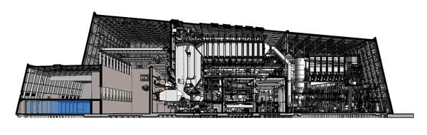
Inside the completed facility
Three trusses supporting the cranes were designed; two were 4m deep spanning 30m and a third was 3m deep spanning 18m. The truss design was developed in conjunction with the fatigue design of the truss connections for the stress ranges derived from the cyclical loading induced from both cranes in operation at any one time.
“As the continual movement of the cranes will cause fatigue to the steelwork connections and load reversal in the truss members, an enormous amount of design work involving hand calculations was required for the truss connection designs.” says Dr Durand
“Overhead cranes of this size supported on long-span trusses would not be a standard approach in the industry,” suggests Mr Diffley. “Simplifying the building load paths and separating the crane induced fatigue load from the building frame was key in designing the structure.”
The trusses supporting the building and cranes not only provide the required open-plan area at ground level for ancillary boiler house equipment, they also form part of a movement joint within the large structure, as they are positioned approximately one third along its entire length.
The waste bunker and its attached administration office block are a key part of the project and were the first part of the steel frame to be erected.
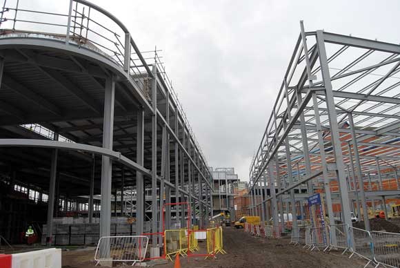
As well as the crane supporting trusses, Severfield also had to erect a series of 37m-long × 3m-deep roof trusses that span over the waste bunker.
The concrete waste bunker measures 25m × 75m and its walls are 23m-high, and forms part of the support system for the structural steelwork.
“Getting all of the trusses installed up and above the concrete bunker would have ordinarily required the use of some large and expensive crawler cranes, positioned outside of the structure’s footprint,” says Severfield Project Manager Michael Moore.
“However, a large ground level opening was left in one of the bunker’s concrete walls, through which materials and cranes could enter. This meant we could assemble all of the surrounding trusses on the bunker’s floor and then erect them as complete pieces, lifted by one 500t-capacity mobile crane which was also positioned inside the bunker.”
Working from inside the bunker and within the project’s footprint saved time and money, and eliminated any obstructions to work going on outside the structure.
Once the bunker steelwork was completed along with the office block, which also contains a control room, the next area to be erected was the tipping hall.
Occupying one end to the overall structure, the tipping hall, as the name suggests, is where trucks will deliver the waste and tip it into the adjacent bunker. The hall is raised 7m-above ground level and to create the necessary large open-plan area a series of 36m-long trusses have been installed.
These trusses were delivered to site in two welded assemblies, then lifted with two cranes into position and bolted together in the air at their final location. A series of 17m-high raking columns forms the tipping hall’s perimeter elevations.
After this area of the steel frame was erected Severfield then began erecting the other end of the building, working their way northwards from the waste bunker.
Sloping columns up to 48m in length form a lean-to structure that encloses the plant’s boiler and turbine halls. The building’s main roof falls from the waste bunker all of the way over the turbine hall to the back of the flue gas hall, which has an eaves level of 39m above ground.
All of the steelwork around and over the boiler and turbine processing equipment is being installed once the majority of the equipment is in place.
“The processing equipment is key to the entire project and so the boiler house and turbine hall had to be fitted out before the surrounding steelwork could be erected,” adds Mr Diffley.
Interestingly, under separate contract to Severfield’s, a further 6,000t of steel is being installed to support all of this vital processing equipment.
Building work is scheduled for completion early in December 2016 and the Dublin Waste to Energy facility will be operational in 2017.