50 & 20 Years Ago
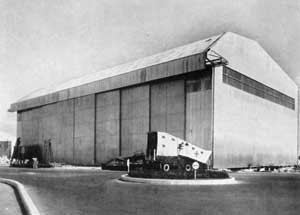
The VC10 hangar at London (Gatwick) Airport
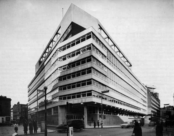
 When British United Airways purchased Vickers VC10 jets the dimensions of these machines, particularly the height of the tail, made it necessary to provide a new hangar to accommodate them for servicing purposes. It is a steel-framed building with double sandwich asbestos cladding and, as will be evident later, no other material than steel could have been employed with such success.
This hangar is unique in the fact that it is possibly the largest of its kind in the United Kingdom and perhaps in Europe. Although it has a floor area of approximately 33,000 sq. ft. only two internal columns are used and they are positioned to give minimum interference to the various types of craft likely to be parked inside. An interesting feature is the provision of a slot in one wall through which the wing of a second aircraft can project, allowing the complete fuselage to be under cover during servicing. By careful planning it has been established that the hangar can in fact house at least three machines simultaneously, e.g. a VC10 in the centre and a Britannia or BAC One-Eleven on each side.
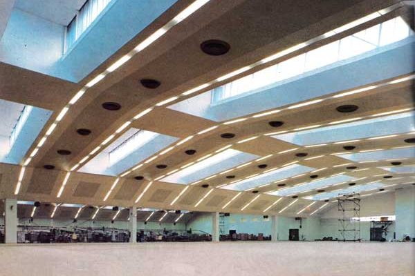
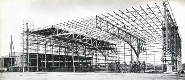
The huge unobstructed door area is made possible by employing a design incorporating four 191-ft. long cantilever truss girders spaced at 60-ft centres and supporting secondary lattice roof trusses transversely at 15-ft centres. The VC10 enters the hangar tail first, the tail positioned between the centre stanchions, where staging along the rear wall enables the mechanics to service without difficulty the tail fin and tail plane. As the fleet increases and additional hangar space becomes necessary, unlimited lateral extension of the hangar by bays of similar construction is a relatively simple procedure.
The overhang of the cantilever girders is 134 ft. and under maximum loading conditions of wind and snow, but excluding the allowed dead weight, a maximum deflection of 6 in. at the tips of the cantilevers is expected. Allowance for this deflection has been made in the design of the side cladding and also in the housing of the top guides to the sliding hangar doors.
The connections between the cantilevers and their latticed support columns are of the conventional rocker type. The reaction from the trusses is transmitted to a system of bearing plates and beams in order to achieve an even distribution of the load over the latticed columns. Restraint to the cantilever frames is provided by tension members in the rear frame of the structure adequately anchored with heavy mass concrete isolated gravity bases. When the cantilever frames were erected and the roof sheeting fixed, the actual deflection of the cantilever tip varied from the calculated deflection by no more than half an inch.
The upper rollers of the hangar doors are specially designed so that vertical deflection of the roof over the doors can be accommodated in very shallow and lightweight top guides. This has resulted in considerable economy of structural materials in the guides and also minimised the concentrated dead loads at the extremities of the trusses. The sliding hangar doors consist of six 50-ft high by 30-ft wide manually operated leaves.
The architects for this project were Clive Pascall and Peter Watson.
 Steel framed hangars for the Middle East

During recent years the Air Ministry has placed orders for a number of large steel-framed hangars for desitinations abroad. For this type of work steelwork has several important advantages over other methods of construction, apart from those concerned with design. For instance, the structural members can be completed in this country, ready for erection, and occupy minimum cargo space when shipping them abroad. On arrival the hangars can be conveniently transported and easily erected by local semi-skilled labour.