Technical
Test on 15m Span Composite Cellular Beam
Mark Lawson and Eleftherios Aggelopoulos of the SCI and Dennis Lam of the University of Bradford present the results from a recent test carried out at the University of Bradford to investigate the behaviour of a composite beam with a low degree of shear connection.
Introduction
Cellular beams are the preferred form of long span construction in multi-storey buildings. For efficient design of composite cellular beams, asymmetric sections are often manufactured in which the bottom flange is larger than the top flange. A further innovation is in the use of 80mm deep deck profiles which allows beam spacing to be increased to 4.5m, and so the effective slab width acting compositely with the long span beams is also increased.
The values for shear connector (stud) resistance given in Eurocode 4 (EN 1994-1-1), when used in combination with these modern decking profiles, have led to problems in achieving the minimum degree of shear connection for composite beams in comparison to the former BS 5950-3. For secondary beams, the number of shear connectors that can be accommodated in a span is limited by the spacing of the deck ribs (typically 300mm for deep trapezoidal profiles), and it is found that even for pairs of shear connectors per deck rib, it is impossible to satisfy the shear connection rules in Eurocode 4 for long span asymmetric beams.
SCI, with support from the Research Fund for Coal and Steel, is on the way to resolving this problem in design to Eurocode 4, and has completed a test on a 15.3m composite cellular beam at the University of Bradford. This is believed to be the longest composite cellular beam test ever carried out. The test was part-sponsored by ASD Westok.
Cellular beams differ in various ways from I-section beams, which suggests that a relaxation in the design rules for shear connection may be proposed, based on the following arguments:
- The openings in the web of the section in cellular beams mean that, unlike sections with solid webs, it is not necessary to develop plastic deformation over the full depth of the cross section at the ultimate bending resistance of the composite section. This has the effect of reducing the strain that is developed in the steel section and also reducing the slip at the ends of the beam.
- The local resistance at the openings often limits the design of a cellular beam and so it is not possible to reach the plastic bending resistance of the beam in mid-span.
- The design of long span cellular beams is generally controlled by deflections at the serviceability limit state, and so the beam is not fully utilised in bending at the ultimate limit state.
Beam details
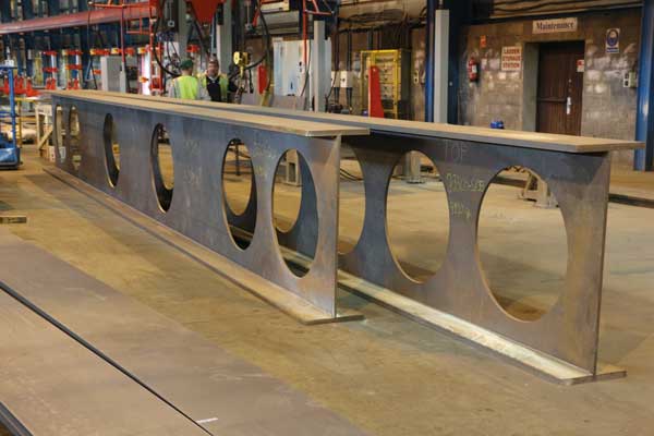
The cellular test beam was representative of a typical secondary beam in modern long span composite construction. The bottom part of the cellular beam was chosen as an HEB 360 section, and the upper part was an IPE 450 section, so that the ratio of flange areas was about 2.4. The resulting cellular beam depth was 565mm after the cutting and re-welding process, and so the span/depth ratio was 27, which is relatively high. The beam was fabricated by ASD Westok.
Fig. 1a: Cellular beam showing decking and shear connectors
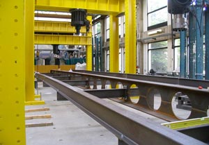
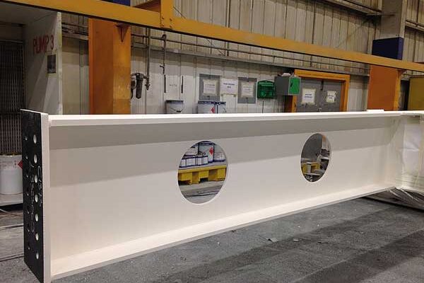
Fig. 1b: Temporary ‘out-riggers’
The 425mm diameter circular openings were placed at 680mm spacing. An elongated opening of 1105mm length was provided at mid-span. Some openings were half in-filled at or near to load points to avoid local failure. The CF 80 decking was delivered by Tata Steel Panels and Profiles, and single 19mm diameter and 125mm high shear connectors were placed in each deck rib (Figure 1a). The calculated degree of shear connection was only 36%, which was less than half of the minimum to Eurocode 4 for the specific beam. The slab depth was 150mm and A193 mesh reinforcement was used, primarily because the slab had to act as a cantilever to resist its self-weight.
A novel system of construction was used to mimic unpropped construction. This was done by bolting projecting I-sections as out-riggers to the web of the beam at 6 locations so that the long edge of the decking could be supported by these sections (Figure 1b,). This is important because it is known that un-propped construction leads to lower shear connector forces and, potentially, to lower slips at the plastic bending resistance of the beam. The I-sections were removed when the concrete had gained its full strength (measured as 30MPa).
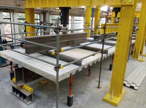
Fig. 2a: Composite beam under loading
The composite beam was subjected to a simulated uniform load from 8 point loads and the critical cross-section was at the load point at 6.7m from one support. A total of 22 shear connectors were placed between the support and this point. The loaded test beam is shown in Figure 2a, and load deflection curves for the various load cycles from working load to ultimate load and then to the failure load are shown in Figure 2b.
The total test failure load was 20.4kN/m², including the slab self-weight (3.2kN/m² approximately), which represented a global factor of safety of 2.5 relative to the un-factored loading of 8.2kN/m² that would have normally been assumed in practice (self-weight plus 5kN/m² imposed loading). The load-deflection graph was approximately linear up to a load of 8kN/m², as evidenced by the low residual deflection and end slip on unloading. At the failure load, the slip between the beam and the slab was 13.5mm at one end and 8.5mm at the other end.
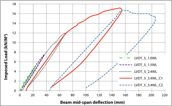
Fig. 2b: Load-deflection graph for each load cycle
In the final load cycle, the compression strain in the top flange was 1065 micro-strain, and the tensile strain in the bottom flange was 1995 micro-strain, which indicated that the bottom flange had reached its yield resistance. The concrete strain was 0.086% which is less than the maximum strain of 0.2% that is experienced by concrete at its maximum strength.
Analysis of beam test
The test beam was analysed in accordance with the method of Eurocode 4 using a shear connector resistance of 70kN obtained from previous push-out tests and which is similar to the Eurocode 4 characteristic resistance when using CF 80 decking. The plastic bending resistance was calculated to be 1798kNm which was close to the measured failure moment of 1790kNm, and shows that the plastic bending resistance was developed despite the low degree of shear connection. The bending resistance to Eurocode 4 using design properties was 1567kNm, which was 87% of the test bending resistance.
The theoretical deflection of the composite beam was 26.6mm compared to a test deflection of 31.5mm at working loads. The difference of 4.9mm is due to end slip caused by partial shear connection and shear deformation at the openings. SCI P355 ‘Design of composite beams with large web openings’ predicts an additional deflection of about 5mm due to the openings alone.
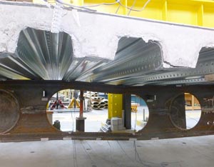
Fig. 3. Shear force applied to elongated opening at failure
A second part of the test was carried out by repositioning the loads so that the elongated opening at mid-span is subjected to shear, and it was found that the shear force at failure was 152kN. The failure mode is shown in Figure 3. The failure load was approximately twice the theoretical shear resistance based on the Vierendeel bending (local bending of the Tees) assisted by local composite action around the opening, and shows that existing design methods are conservative.
This test is being analysed in detail by SCI and University of Bradford, and a second long span beam test is planned to be performed in mid-2014. The next test will address either an intermediate degree of shear connection using pairs of shear connectors or possibly an alternative beam size and span in order to provide more detailed information on other design cases. Based on these tests, new guidance will be prepared to support the design of cellular beams for low degrees of shear connection.
Acknowledgement
The research leading to these results is part of a joint project by the Steel Construction Institute, the Universities of Stuttgart, Luxembourg, and Bradford and ArcelorMittal, with part-funding from the European Community’s Research Fund for Coal and Steel (RFCS) under grant agreement n° [RFSRCT-2012-00030].