Projects and Features
Taegu Stadium, South Korea

A world-class stadium has been built in Daegu Metropolitan City, South Korea. It has a dramatic steel arched roof. Mike Stephens and Chul-Hee Kang report.
FACT FILE: Taegu Stadium, South Korea
Owner: Taegu Metropolitan City
Area of Park: 19.5 million m²
Area of Sports Park: 1.93 million m²
Main Usage: Sports complex (soccer and track and field events)
Secondary Usage: Events, concerts & exhibitions
Capacity: 70,140 seats
Parking Capacity: 2,435 vehicles
Total steel weight: 4,350 tonnes
Area of Park: 19.5 million m²
Area of Sports Park: 1.93 million m²
Main Usage: Sports complex (soccer and track and field events)
Secondary Usage: Events, concerts & exhibitions
Capacity: 70,140 seats
Parking Capacity: 2,435 vehicles
Total steel weight: 4,350 tonnes
Taegu (Daegu) Stadium is located in Daegu Metropolitan City, South Korea. It was conceived as part of a complex which comprise Korea’s and Japan’s joint effort to host the 2002 World Cup and the 2003 Summer Universidade. The project symbolises the strengthening bonds between Korea and Japan. It is the “jewel in the crown” of the purpose-designed Taegu Grand Park, an area of some 19.5 million m².
Commissioned by Taegu Metropolitan City, the architect in charge of the Taegu Stadium project was Idea Image Institute Architects and Planners, Co. Ltd.
Location
The Grand Park is 10km east of Taegu centre and lies around Mount Daedeok. A major factor was harmonisation with the surrounding environment and the incorporation of natural elements in the design.
The stadium is designed to complement the scenery provided by Mt Daedeok to the south and the lines of the stadium reflect those of the mountain. The open roof also provides a frame for the mountain when viewed from inside.
Concept and design
Stadia are public buildings, so they share many common or repeatable elements for a largescale construction. However, the ratio of profit to initial investment is low, while the maintenance cost is high, so stadia are not economical buildings. Therefore, modern projects need to adopt a different approach in order to be financially viable. In this plan, convenience and safety were chosen as themes, and five related elements were isolated: economy, multi-purpose usage, functionality, creativity and symbolism.
The resulting design form took the following concepts:
- Global union – the roof of the stadium is abstracted from the image of the earth encompassing all people under one cover
- Harmony with nature – Mount Daedeok, which lies to the south, is used to strike a balance between the natural and artificial; and
- Traditional Korean aesthetics – the stadium roof curve mimics that of the traditional folk house
As the primary function of this facility is as a sporting venue, it was vital to consider the need for a well-ventilated pitch above everything.
Beyond the 2002 World Cup and the 2003 Universidade, the site is to have further uses as a regular sporting venue, including football, track and field events, and concert and exhibition halls, as well as offices. Creating a truly multipurpose site, which was also profitable, was a major challenge for the architects, not only in terms of overall functional design but also with regard to the development and management of facilities, such as car parking, seating and spectator mobility.
Stadium roof
Atkins was initially approached at the scheme stage of the project to provide technical input into the design. The company’s remit addressed the simplification of the layout of the roof structure, the provision of a more efficient structural system and a practical solution for the membrane covering.
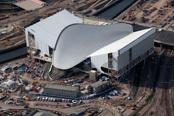
The roof is composed of fabric membranes supported by the steel roof. According the original architectural concept, the roof has a shape covering over 70% of the visitors’ seating with minimum supporting points.
Design concept and planning

Fundamental to the success of this project was planning and development work.
Wind Tunnel
A physical 3D scale model was created and subjected to wind tunnel testing at the BMT laboratories in West London. This enabled Atkins to make an accurate assessment of the wind pressures on the surface of this complexshaped structure and to optimise the design.
The scale model was placed in the wind tunnel on a rotating table and the surrounding topography mimicked to reproduce the turbulence created by wind across the terrain. Pressure readings were taken at over 200 locations and for twenty-four different wind directions. The results were then interpreted for analysis purposes, and used for the design of both the membrane and the steelwork.
Computer-aided modelling
Computer aided modelling proved invaluable to the understanding of the interfaces between the elements of the steelwork. The complexity of the geometry for the roof design meant that CAD was the only way to determine how the details worked and how they would look when constructed.
Materials
The roof structure comprises the following elements:
- Steel arch trusses and PTFE/glass fabric were selected as the ideal materials for the roof, along with stainless steel cables and fabric clamp plates manufactured from aluminium
- The PTFE (Poly Tetra Fluor Ethylene) coated glass-reinforced fabric has a light translucency of 13+3% and maintains an illuminance above 1,300 lux on a clear day. The material maintains its white surface, it prevents acoustic echoes, and it has low self weight and high tensile strength. Within the roof there are service walkways in the front and rear arches, and along the secondary trusses, to provide access to some 40 tonnes of lighting and audio equipment
Fabric Membrane
Each roof consists of 24 individual panels of PTFE fabric. This membrane is a structural element, with a life span in excess of 25 years. The panels were stretched over six slender arched purlins, located at equal spacing along the secondary trusses. The purlin centres vary from 10.4m for the central trusses to 3.6m on the outer bays. Each panel side is fixed to the secondary trusses and the ends are fixed to the primary trusses.

Tensioning of the membrane is critical in order to achieve not only a good finish, but also to ensure that loads are efficiently transferred through the whole structure. In a positive pressure case, the membrane dips between the purlins, increasing the stress in the longitudinal direction of the fabric. In an uplift case, to avoid ‘billowing’ of the membrane panels it was necessary to include slip cables, which lie in the plane of the fabric to help hold the membrane down.
The membrane provides lateral restraint to the purlins, and the connection between the purlin and the secondary truss is designed to rotate about its longitudinal axis. This enables the loads to distribute equally in the membrane panels during pre-tensioning. In the event of a failure in a fabric panel, the purlin will rotate and destress the whole bay, thus preventing permanent damage to either the purlins or the membrane.
Steelwork
After the tender period, the stadium roof structure was reviewed in a value engineering exercise. The changes resulting from this included the removal of 12,000m² of aluminium cladding from the front and rear arches. With the secondary support structure no longer required, and the reduction of the dead load on the structure, this enabled Atkins to reduce the steel tonnage for the main arches.

The front and rear arches, although similar in form, perform very different functions. The 6m square front arch has a clear span of 273m, a maximum rise of 28.3m and is inclined to the vertical by approx. 30º. It comprises four 763 mm diameter tubes with 273mm diameter bracing between. It connects to the rear arch at each end on top of the reinforced concrete support towers.
The rear arch, again square, (but only 4m deep) consists of 508mm diameter tubes with diagonal bracing and is supported at thirteen locations along its length on top of the diagonal raking columns.
As the front arch leans back towards the rear arch, a load is transferred through the secondary trusses back into the rear arch. This acts as a tie, distributing the vertical component of the load to ground through the columns, and the horizontal component in tension back to the main tower supports.
The main supports for tower are founded on rock at the southern end and compacted fill at the northern end. They are large hollow reinforced concrete structures, with raft bases, which are tied into the underlying rock with rock anchors. The cantilevered towers are subjected to a horizontal thrust of 3,200 tonnes.
The anticipated tower displacements due to this lateral force were obtained from careful analysis. The results of which were then used for the analysis of the roof, giving an upper and lower bound spring stiffness for the main arch supports so that the second order effects of the deflections were included in the forces generated.
The structure was also designed to accommodate the forces generated by the expansion and contraction of the structure for the wide range of temperatures expected in Korea as well as seismic loads.
Secondary trusses, prismatic in form, span between the front and rear arches, their length varying between 25m and 66m. The top section comprises four rectangular hollow sections, 1.5m apart, jointed with a thick plate, which also acts as a gutter section.
Drainage
The roof utilises a state-of-the-art syphonic drainage system, which removes excess water more quickly than conventional systems. Water runs off the membrane panels into the gutters around each perimeter and transfers along the secondary trusses into a system that discharges along the rear arch. The water collects at the tower location from which point it is discharged.
Construction Method
The individual elements that comprise the primary arches were delivered in maximum 11m lengths. These were then welded up to form the box-shaped truss on site.
Temporary supports were provided along the rear of the stand to provide stability for the rear arch and column construction.
The small sections of the front arch were welded together inside the stadium into five pieces (approx. 70m in length). These sections were then lifted onto the substantial temporary cantilever support towers, where they were welded together. Once the primary and secondary structures were finally in place, the temporary support towers were released and the movement of the arches and end tower supports carefully monitored.
Conclusion
Careful planning has been the hallmark of the Taegu Stadium project. From the demands of the abstract and functional concepts considered during the design process through the environmental constraints of the site and the financial and physical demands of construction, all parties involved have worked to create a unique building, which will not only bring pleasure to those who use it, but which also serves as a prototype for future stadia globally.
Mike Stephens, is a Project Engineer at Atkins. Chul-Hee Kang is an Architect.