Projects and Features
Steel is ready for BIM
The steel construction sector is ahead of the game as far as implementing the use of Level 2 BIM before next year’s Government deadline. Nick Barrett reports.
Construction’s biggest client – the Government – demands that all of the projects it funds use Level 2 Building Information Modelling (BIM) by next year. The 2016 deadline applies to Northern Ireland projects procured by its Centre of Procurement Expertise (CoPE), Scotland has until 2017.
This demand, announced in 2011, set the construction industry off on a mission to find software and people with experience in using BIM. Along the way major issues have seemingly arisen in relation to matters like insurance, copyright, commercial confidentiality and the industry’s ability to work in the collaborative ways implied by BIM. Doubters about the industry’s ability to be ready in time have regularly surfaced.
Steelwork Contractors have been in the enviable position of being able to take a more sanguine view than most as they have in fact been using the type of 3D modelling and design software that will be commonplace when a project is BIM driven for many years.
Dr David Moore, Engineering Director of BCSA said: “One of the reasons that Steelwork Contractors are ready for BIM is their use of 3D modelling and their ability to work in an electronic environment. Steelwork Contractors have been using 3D modelling for many years, are familiar with the software and have the necessary IT systems, skilled people and the processes in place to embrace BIM now.
“The software appropriate for BIM is any software application that can manipulate objects and has the ability to import and export data to other software applications being used by other members of construction teams.
“Steel-framed structures are well suited to the BIM process as individual steel members can be clearly identified and objects allocated to them easily”
Dr Moore says a key aspect of BIM is the transition from working with documents to working with data by using the digital environment where information is recorded and stored electronically. This aspect of BIM requires a platform to store and share data, he explains. “Web-based software can be used as a service platform to store and share electronic project-related information between different members of the project team working in different locations. This technology replaces sets of data held locally by individual members of the project team and allows authorised team members access to the relevant information.”
Each key member of a project team, including the Steelwork Contractor, will be required to produce a 3D model of their scope of work (i.e. in the case of the Steelwork Contractor the steel frame) based on the original model provided. The individual 3D models developed by each key member of the project team are then transferred to a single electric platform, which is usually managed by the Principal Contractor, where they are linked together to create what is known as a ‘Federated Building Information Model’.
Dr Moore says: “Linking the models this way allows each project team’s members to work with related data in using their own 3D software. It also provides a means to coordinate the design and to detect any clashes.”
During a BIM project there are a number of key information transfer requirements at a variety of different stages in the construction process. During the design and delivery process the exchange of information to the Steelwork Contractor from the Principal Contractor is likely to be in a variety of formats. Although all the information will be electronic format, some information will be contained within 3D models and other information in 2D pdf documents.
At the handover and close-out stage all necessary information about the steelwork should be included in the handover documentation. The information provided at this stage will again comprise both 3D model information and supplementary 2D pdf documentation. This information will be in three sections:
• 3D model files
• Documents and 2D drawings
• COBie-UK-2012 data
3D Model files
3D BIM files should be as-constructed and provided in a suitable format. The as-constructed model should represent the as-constructed project in content and dimensional accuracy. This does not mean that models need to be updated to reflect deflections and construction which is within the allowable tolerances, but any construction or manufacture which is out of tolerance should be updated within the model. 3D clash files should also be issued.
Documents and 2D drawings
2D drawings should be updated to reflect the as-constructed state and issued as 2D pdfs. As the BIM process develops it is possible that some Clients may not require 2D drawings to be issued at the handover stage.
Key non-geometric information for steelwork which may be included within the 2D drawings set may include:
• Member schedule
• Material grade
• Material sub-grade
Non geometrical information which is required to be provided in addition to 2D drawings and issued electronically in pdf format will typically comprise:
• Manufacturer’s operation and maintenance documentation
• Testing and commissioning records
• Health and safety information
COBie-UK-2012 data
Construction Operations Building Information Exchange (COBie) is a data format focussed on delivering non-geometrical building information such as schedules of proprietary items and product data sheets, warranties, test certificates and commissioning information and other non-geometrical building information. It is likely that Steelwork Contractors will not be required to provide COBie information, but the Steelwork Contractor should clarify the extent of the information to be provided at contract award.
Dr Moore concludes: “We should remember that the 3D modelling aspects of BIM uses design software, not drawing software and not BIM software. There isn’t a specific BIM software, and the sort of software that Steelwork Contractors have been using for many years has all the capabilities required.
“The steel sector is ready for BIM and there is no reason why the rest of the construction supply chain shouldn’t be ready in time to meet the government’s deadline.”
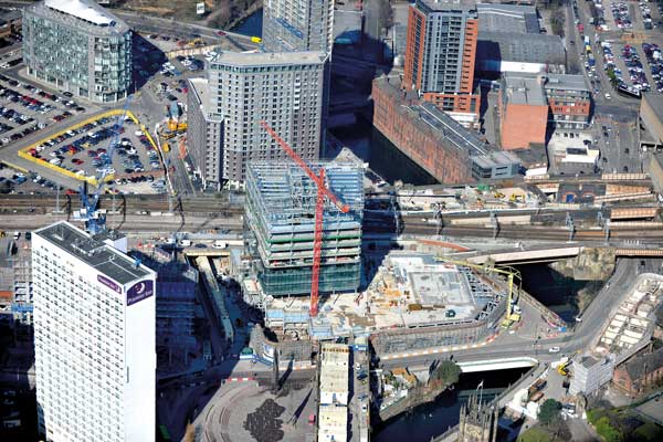
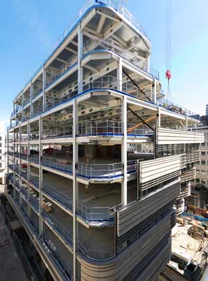 St James’s Market
A BIM approach has ensured the prestigious St James’s Market project in central London is progressing efficiently and on schedule.
Working on behalf of main contractor Balfour Beatty, William Hare has erected 3,500t of steel for the two adjacent eight-storey commercial blocks that constitute the St James’s Market project.
Known as 14-22 Regent Street and 52-56 Haymarket both buildings have made extensive use of fabricated cellular beams. These sections have 350mm deep holes to accept the services within their depth, as well as being stiff enough to span the required grids which are up to 18m.
“To make sure all of the services were integrated within the floor beams and there were no clashes anywhere on either of the two frames we were reliant on the early production of a BIM model,” says Balfour Beatty Structural Manager Dylan Wright.
“It was important that all of the project team was involved and this will ensure a quicker construction programme.”
Getting the entire team to buy into a BIM approach is something William Hare’s Project Engineer Adam Suthers agrees with: “It takes more than just a BIM model, it requires collaborative BIM personnel which is what we have on this project.”
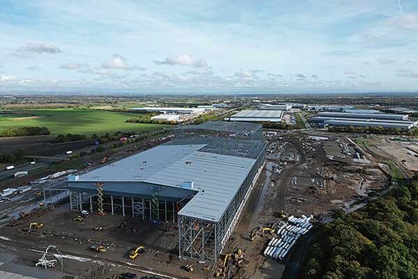
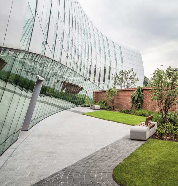
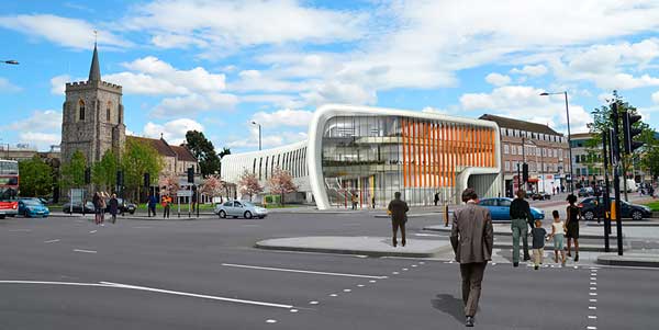 The Curve cultural and learning centre, Slough
“Our expertise in BIM and 3D modelling using Tekla software has been a great benefit on this project, enabling us to integrate the original architect’s model with our own,” says Caunton Engineering Contracts Manager, Phil Ratcliffe.
Working on behalf of Morgan Sindall, steelwork contractor Caunton Engineering has erected 370t of steel for this highly complex project.
As its name suggests this structure is a steel-framed curved rectangle in shape and plan. Each of the building’s elevations feature either cantilevers or sloping and curving façades, with the main north side presenting the most striking aspect with a long sweeping, predominantly glazed, elevation looking on to the adjacent listed St Ethelbert’s Church.
The three-level building is 89.7m long, 15.5m high and has a width which is 34m at its maximum and 16.5m at its narrowest. With an overall floor space of 4,500m² the centre will include a library, café, office space and a 280-seat performance space.
Constructing a building with this kind of complex shape brings with it a whole host of geometry and setting-out challenges. The use of a BIM model, shared between the entire project team made the design process less onerous.
Peter Brett Associates Project Engineer, Mark Way adds: “BIM was the best solution as it allowed everyone to see the same model, and this made it possible to detect any possible problems well in advance.”