SSDA Awards
SSDA 2009 – Other finalists
30 Crown Place, London EC2

30 Crown Place image courtesy of Ramboll
FACT FILE: 30 Crown Place, London EC2
Architect: RHWL Architects
Structural engineer: Ramboll
Steelwork contractor: Rowen Structures Ltd
Main contractor: Skanska
Cost consultant: Davis Langdon LLP
Development manager: City Offices Real Estate
Client: Greycoat Crown Place Limited Partnership
Structural engineer: Ramboll
Steelwork contractor: Rowen Structures Ltd
Main contractor: Skanska
Cost consultant: Davis Langdon LLP
Development manager: City Offices Real Estate
Client: Greycoat Crown Place Limited Partnership
The project at 30 Crown Place is a £60M 18 storey high commercial office development offering 17,500m² of grade A office space in the City of London.
By adopting a lightweight composite steel superstructure and steel substructure, the project team was able to reduce the foundations and reuse piles where possible. The floors act as a diaphragm between the two cores, formed from composite beams. The structural system incorporates the building services within the same depth increasing the efficiency of the system.
The larger lower floor plate rises to ten floors, above this point a smaller floor plate continues to high level. The change between the two is facilitated by a high level steel transfer truss which is used to suspend the column hangers to the southern facade, minimising the number of columns required at the lower levels of the building.
Alan Bunting, Ramboll Project Engineer, says: “The column transfer was integral to the scheme and provides an open plan reduced column office space.”
Constructing a frame with this roof truss created a challenge. The hangers needed the truss and the truss needed the floors to be in place, which in turn, relied on the hangers. The solution was to build a temporary truss, between the 8th and 9th floors, from which the hangers could be constructed and supported until such time as the permanent truss was ready to receive their load.
The building loads where transferred from the temporary truss to the roof truss by pushing the column hangers and all nine floors, up to meet their connections. Large hydraulic jacks were used to push against the lower truss, while monitoring stations on three floors reported its movement.
“Without the inherent capabilities of steel the project could not have been achieved,” says Mr Bunting. “Steel was the only cost effective material to allow the integration of the structure and services within the floor zone, while providing minimal columns.”
40 Portman Square, London W1

FACT FILE: 40 Portman Square, London W1
Architect: Squire and Partners
Structural engineer: Arup
Steelwork contractor: Graham Wood Structural Ltd
Main contractor: BAM Construction Ltd London
Clients: Delancey, Standard Life Investment Funds
One of the main client objectives for 40 Portman Square included delivering a first class office development to attract financial tenants to a traditionally unfashionable London location.
Steve Peet, Arup Project Engineer, says this has been achieved in style with a building providing almost 9,300m² of office space over seven floors and two storeys of residential accommodation above.
“A total building cost of £36.5M and all offices pre-let six months before completion at average rents of more than £100 per square foot demonstrates the market’s reaction to the development and its cost effectiveness,” says Mr Peet.
The quality of the office accommodation has been described as exceptional. The building contains some of the largest floor plates in the West End, providing column free space with abundant natural daylight in all sides.
The structure is a steel frame of long span fabricated beams and composite floors about a central braced steel core. The central core and long span floors allow for all office levels to be free of internal columns. A novel suspension system within the dry lined walls of the residential floors permits the 42m wide northern elevation of the sixth floor office to be entirely unobstructed by columns.Steel was the only realistic choice for the long span floor beams in order to integrate the services, while the weight saving determined that single piles for each column were feasible with the consequential saving to cost and programme.
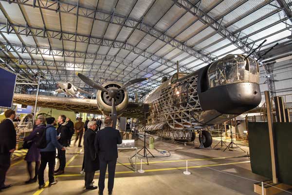
The Tank Museum, Bovington

FACT FILE: The Tank Museum, Bovington
Architect: Kennedy O’Callaghan
Structural engineer: AKS Ward
Steelwork contractor: Bourne Special Projects Ltd
Main contractor: Norwest Holst Ltd
Client: The Tank Museum
The Tank Museum has the world’s largest collection of tanks. More than 250 military vehicles, some dating back to before WW1, can be seen at the museum and more than 100,000 visitors per year flock to the site.
A new display area has been constructed adjacent to the existing museum which also includes an administration block, cafeteria, main entrance hall and a 20m-high viewing tower.
The display area was formed by a series of trusses, eight in total, which span 36m and fan-out from the central entrance hall area to form a large column-free area.
A feature saw tooth roof of the main display area is also formed by the trusses. These large sections radiate out from 4.2m centres, at the entrance hall, to a maximum 10.4m centre arrangement near the building’s perimeter. Connecting the trusses, to form the roof structure, are an arrangement of diagonally placed hot rolled rafters and more then 30t of Metsec supplied secondary steelwork.
“The saw tooth roof was designed to allow natural daylight to easily penetrate the display area below,” explains Ivor Robinson, Contracts Manager for Bourne Special Projects.“ However, this arrangement means the roof slopes in a number directions and we had to design some time-consuming connections.”
Because the majority of the display area needed to be column-free which will aid the movement of exhibits in, out and around the hall, bracing was ruled out in most areas.
“We were able to put some feature bracing in one bay near to the perimeter wall,” explains Ken Richards, AKS Ward Project Engineer. “But elsewhere the roof rafters act as the bracing.”
5 Aldermanbury Square, London

Replacing a 1960s 18 storey high London office block with a modern flexible structure with one extra floor was the main challenge associated with this project.
“We squeezed in an extra floor by compressing the structure around the horizontal service voids, while the selection of core-ten composite box columns allowed us to place perimeter columns in the cladding zone, and gave us uninterrupted column free interior walls,” says Simon Groves, Ramboll Project Engineer.
These innovations with the project’s steel frame increased the revenue for the building and also created flush perimeter walls which give extra flexibility.
The adaptability of the steel frame came to the fore on the ground floor where new hanging retail mezzanines were added. On the 13th to 16th floors, which had been let to a single tenant, a dedicated communicating staircase was provided by creating openings in the secondary beams.
“Many of the perimeter columns are inclined in two directions and they required precise engineering and milling,” says Richard Tarren, Severfield’s Project Manager. “The members are also box columns which were later infilled with concrete, so during fabrication we had to install reinforcement.”
The building features curving elevations on the east and west facades to reduce the visual impact of its volume.
FACT FILE: 5 Aldermanbury Square, London
Architect: Eric Parry Architects
Structural engineer: Ramboll
Steelwork contractor: Severfield-Reeve Structures Ltd
Main contractor: Bovis Lend Lease
Development manager: Hanover Cube
Client: Scottish Widows
The Curve, Leicester

FACT FILE: The Curve, Leicester
Architect: Rafael Viñoly Architects
Structural engineer: Adams Kara Taylor
Steelwork contractor: William Hare Ltd
Main contractor: Bovis Lend Lease
Client: Leicester City Council
Structural engineer: Adams Kara Taylor
Steelwork contractor: William Hare Ltd
Main contractor: Bovis Lend Lease
Client: Leicester City Council
The Curve, otherwise known as the Leicester Performing Arts Centre forms one of the main elements of a new Cultural Quarter rapidly taking shape in Leicester’s St George’s district.

Inside the four level 13,000m² building there is a main foyer and two auditoriums. The main 750-seat theatre and the smaller 350-seat venue are conceived as islands containing balconies arranged in an intimate manner that helps control acoustics.
Jim Dunn, Project Director for Adams Kara Taylor, says: “We had to deal with a very tight and confined inner city site, which ultimately dictated the shape of the building.”
In order to maintain the transparent vision for the structure it was decided to have as few view-blocking columns along the facade as possible. To achieve this, there are in fact no structural columns and everything is suspended from the roof. This includes the facade and walkway, a 125m² conference room and all heavy plant.
Steelwork contractor, William Hare erected more than 3,000t of steel for the roof structure, with the remainder of its final 5,200 tonnage being accounted for by two steel-framed shoulder blocks which house administration offices, workshops and changing rooms.
The steel roof is made up of a number of 6m deep trusses which have varying spans from 25m to 30m. The roof is also functional, explains Mr Dunn. “The plant room hangs from the bottom cord of the trusses and acts as ballast.”
The Bridge Academy, Hackney
Image courtesy of Samma Fisher Payne/BDP
FACT FILE: The Bridge Academy, Hackney
Architect: BDP
Structural engineer: BDP
Steelwork contractor: Watson Steel Structures Ltd
Main contractor: Mace Plus
Clients: Department for Children, Schools & Families; UBS AG
Structural engineer: BDP
Steelwork contractor: Watson Steel Structures Ltd
Main contractor: Mace Plus
Clients: Department for Children, Schools & Families; UBS AG
Bridge Academy is part of a national government initiative to build state of the art schools in the country’s worst performing areas.
The brief was to design a city academy on a tight site alongside the Grand Union Canal and maximise space. The resulting £33M, seven storey building provides an internal area of 10,250m² with 5,500m² of external space on the 6,000m² site.Steel was chosen as the structural material to meet the demands for long spans with integrated services, heavily loaded terrace area as well as truss elements and tension members.
The main building consists of a horseshoe of accommodation that terraces down to the open side with circulation galleries provided on the inner perimeter. In the centre of the horseshoe and suspended from the inner perimeter is a two storey structure that houses the learning resource centre and ‘village square’.
The suspended structure enables the ‘village square’ to be a completely column free and flexible space.
The inclined inner perimeter is formed from 12 CHS sections arranged as an inclined truss and clad in lightweight ETFE.
All teaching spaces are naturally ventilated with air introduced at the outer perimeter and extracted via the circulation galleries where excess heat is recovered and re-used. The underside of the project’s profiled metal decks are coated with a high emissivity paint developed by NASA that improves the heat transfer between the air and the concrete via the steel surface.
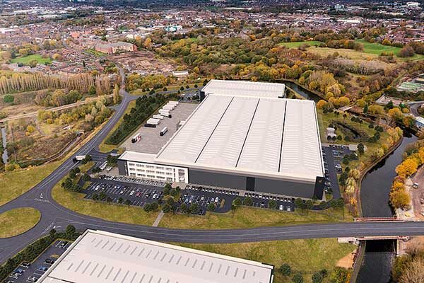
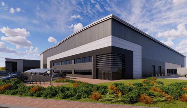
The University of Sheffield Advanced Manufacturing Research Centre with Boeing, Rolls-Royce Factory of the Future

FACT FILE: The University of Sheffield Advanced Manufacturing Research Centre with Boeing, Rolls-Royce Factory of the Future
Architect: Bond Bryan Ltd
Structural engineer: Buro Happold
Steelwork contractor: Conder Structures Ltd
Main contractor: The Bowmer & Kirkland Group
Client: University of Sheffield
The £15M University of Sheffield’s ‘Factory of the Future’ was designed as an exemplar facility embracing renewable technologies and it is one of the UK’s first carbon neutral buildings.
“The inclusion of 20 sustainable and specified environmental features, plus the tight programme meant steel was the only option,” says Jason Hensman, Conder’s Managing Director.
The building has achieved an ‘Excellent’ BREEAM rating and Geoff Halliwell, Director at Bond Bryan Architects says: “The structure has low environmental impact and has achieved the highest BREEAM rating for any building of its kind.”
The building’s steel frame consists of universal beam and columns, with cellular beams for office floors. The structure extends above single storey height along two sides with the front zone connected to the rear areas via three architectural bridges.
The roof structure was formed from steel tubing and Macalloy bars, while two trusses in each skylight add to the overall appearance and allow light to penetrate the building.
Buro Happold’s Project Leader, Jason Gardner, sums up: “The carbon neutral target was achieved through a combination of good structural and building design.”