50 & 20 Years Ago
Set square in Steel
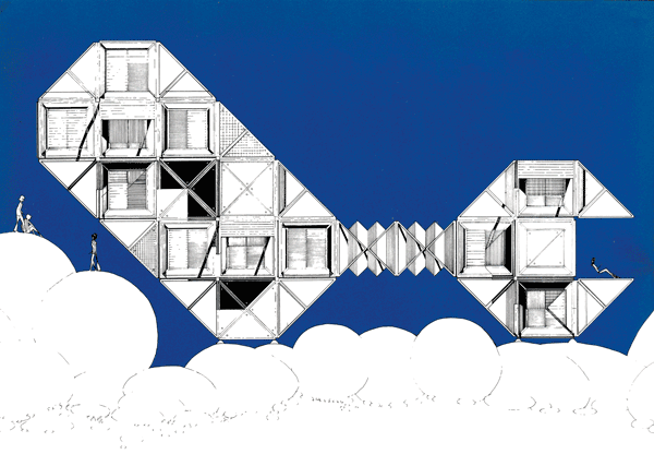 From BUILDING WITH STEEL November 1970
A few years ago Ken Bartlett designed a steel housing system for a competition organized by the then ECSC. He has recently developed his ideas further and the Mk II version is described here. There are no immediate plans to go into production, though one day – who knows? – but then Bartlett is already thinking of Mk IlI.
Design Philosophy
Producing an industrialized building system in steel was an opportunity to update house form to bring it into line with 20th Century technology. It was felt that the traditional house plan with three bedrooms up and living room below has existed too long, rigidifying living habits, and failing to exploit new building materials and engineering technology to the full.
It is important to make the most of every square metre of floor area. The all-purpose room will be one approach, ensuring that the whole interior of the dwelling can be used at all times during the day. It is uneconomical to allot one half of the house to sleeping and one to living, when with purposeful planning the whole area can be used for living. Again useable floor space is often reduced by loose fittings. In this scheme it is proposed that unrequired fittings, perhaps additional chairs, be stored in the interfloor space accessible from the floor above for immediate use when required.
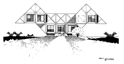
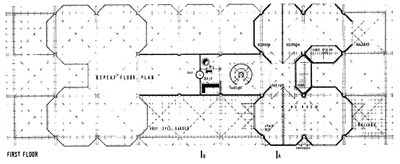
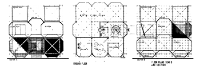 In fact everything should be capable of addition, reduction and rearrangement. On a larger scale, clip on cupboards and storage units can be added or removed as necessary, also rooms, balconies and porches can be added or taken away.
The rigid use of a module vertically and horizontally will go a long way to give aesthetic control over future additions and alterations which may be made to the dwelling, but a comprehensive handbook, like a car maintenance manual, will be required to instruct where and where not to bolt on an extra room.
Twentieth Century technology also gives opportunity for complete environmental control. Ventilation can be provided mechanically where it is needed at the correct temperature. Similarly, light should be provided where it is needed at the intensity it is needed. This does not preclude daylight and sunshine (without solar gain), essential to the tolerant living atmosphere. Engineering services become more an essential consideration as the house becomes more ‘machine’ orientated. In this scheme these are accommodated in the interfloor space with easy access for maintenance and alterations.
Modifications to Original Project
The above was the design philosophy in the original project but modifications have been made to this to make the scheme simpler and more economical, without losing any of the original aims.
The prime consideration was to reduce in size the steel pressing. This is done by the reduction of panel size to a triangular form which combined and fitted to the structural member forms the largest solid panel. It is also intended to reduce the number of variables even further and yet not lose the flexibility of the system. This is done by designing pieces which, when used in other planes, perform other functions.
The same pieces, for example, are used to make up walls, floors and roofs. All components are designed for as many varied functions as possible. Economies are made on the original project by the omission of certain repetitive elements unnecessary to the structure. For example, the structural element was in many cases superfluous but had to be used for the continuity of the system or the purity of the method. The revised version allows the structural element to be omitted when not needed. In a multi-storey structure a four-column cluster formed by the use of four structural elements is required at the lower floor level, but three- or two-column clusters only are required on upper floor levels.
As the components can be used in various positions to fulfil various functions, this thesis can include the whole structure. The structure element gives diagonal bracing enabling the dwelling assembly to be erected upside down or on its side and the 3m cubes give workable floor space in any direction. This is intended to illustrate the various dwelling profiles that can be incorporated into a group of dwellings erected in the estate context.
Materials
External panels are of plastic coated steel with insulation backing. The panels will be in a variety of colours and canvas sun and wind baffles can also be tied in the triangle formed by the bracing of the structural element.
The components illustrated form only the carcass of the dwelling, though it is intended that the back of the panels are treated as the finished interior surface. To the carcass will be added interiors to cupboard fittings, bathroom and kitchen fittings and internal doors and partitions to complete the dwelling.
The fire resistance to the structure element is suggested in the traditional way with 25mm asbestos casing to the square section tubes. Then plastic coated steel casings detailed to fit the pressed panels. However, a more imaginative and certainly economical way would be to liquid fill the square tubes themselves. If the dwelling is subject to fire the continuous loop of the structure element would circulate the liquid, like a gravity feed heating system, thus keeping the steel temperature down for the time required by byelaws. This, however, is something to be worked out in the Mk Ill design.
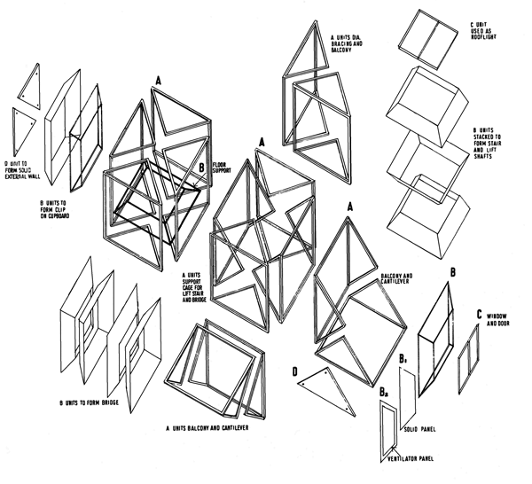
UNITS REQUIRED TO COMPLETE CARCASS OF STRUCTURE
A STRUCTURE
Using 50mm square section cased with 25mm asbestos with plastic coated steel finish
These are bolted together to give ‘spider web’ construction
For 2 and 3 storey structure the 3m cube can be formed from 2 A units but for greater heights 4 A units are required on lower floors giving centre column cluster of eight 50 mm square tubes. Extra lateral bracing can be given by solid infill panel C where required
These units can be put together to form cantilevers, balconies, diagonal corner bracing and diagonal balconies, bridge bracing and lift shaft bracing
B CLADDING FRAME
This unit will support projecting windows framing to floor, convert with solid panel C to clip on cupboard units, form rooflight framing, form cladding frame to bridge staircase and lift shafts
B1 CLADDING B2 TO B
This unit used externally is clad with plastic coat sheeting with ventilators where required for room ventilation
C GLAZING
Double glazed units with blind between to form fixed glazing single or double doors and fixed roof lights
D SOLID PANEL
Of plastic coat sheet steel with thermal insulated backing. This unit gives solid wall units lateral and diagonal bracing, underfloor and roof panels.

