Projects and Features
Safeguarding road and rail with steel
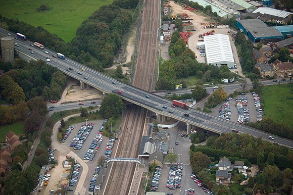
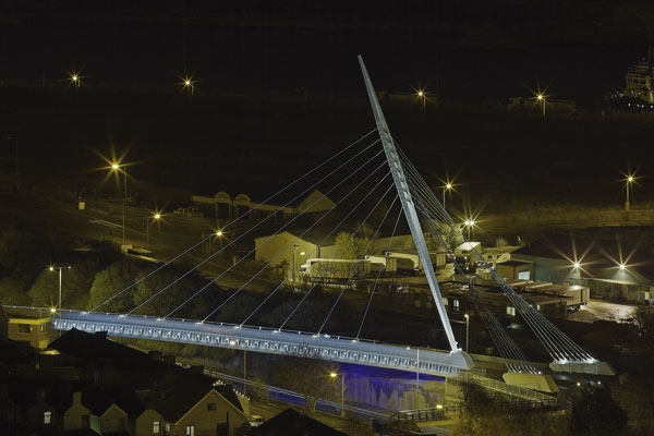
The A14 viaduct spans Brampton Road and the East Coast Main Line near Huntingdon Station
The installation of new steel beams will enhance the safeguarding of a viaduct that carries a busy trunk road over the East Coast Main Line railway.
FACT FILE: A14 Huntingdon Railway Viaduct safeguarding works
Main client: Highways Agency
Main Contractor: Costain
Structural Engineer: URS
Scheme Manager: CarillionWSP
Steelwork Contractor: Cleveland Bridge
Steel tonnage: 500t
Built in 1975 the Huntingdon Railway Viaduct carries the busy A14 dual carriageway over the East Coast Main Line railway adjacent to the market town’s train station.
Traffic volume along this important highway – which connects the port of Felixstowe with the Midlands – is increasing year on year. Coupled with ongoing deterioration of the parent structure, this has necessitated some innovative steel construction to safeguard the structure.
The viaduct is a pre-stressed concrete six span structure with an overall length of 225.8m. The central span crosses the railway and carries the A14 over another bridge for Brampton Road; a busy route into Huntingdon town centre. Within this central span a pair of concrete half-joints support a suspended span directly above the railway.
“This is a vitally important viaduct and one which has been modified with steel before this current project,” explains Mark Hatcher, URS Project Manager. “Back in 2003 the viaduct had interim strengthening measures applied consisting of a series of new steel beams beneath the central spans, to provide an alternative load path to the deteriorating concrete half-joints. In the event of a half-joint suddenly failing, the steel beams would ‘catch’ the suspended span and prevent it from falling onto the railway. ”
This work only had a design life of 12 years as it was anticipated the structure would be decommissioned or subject to modifications as a consequence of detrunking this part of the A14. At that stage the depth of the steel beams had to be limited to 0.8 m in order to avoid imposing a headroom restriction on Brampton Road.
Alterations to this part of the A14 have recently been out for consultation, but the works being undertaken will restore the original 120 year lifespan of the central part of the structure. This will safeguard the viaduct for the foreseeable future whatever the outcome of the consultation process.
“As well as the lifespan of the previous works coming to an end, a review had concluded that increased traffic loading, combined with the ongoing deterioration of the half-joints, would increase the likelihood of the half-joints failing,” says Paul Sinfield, Highways Agency Project Sponsor. “If this was to happen the viaduct could not be repaired without lane closures and major disruption on the A14. It was therefore necessary to develop a more resilient solution.”
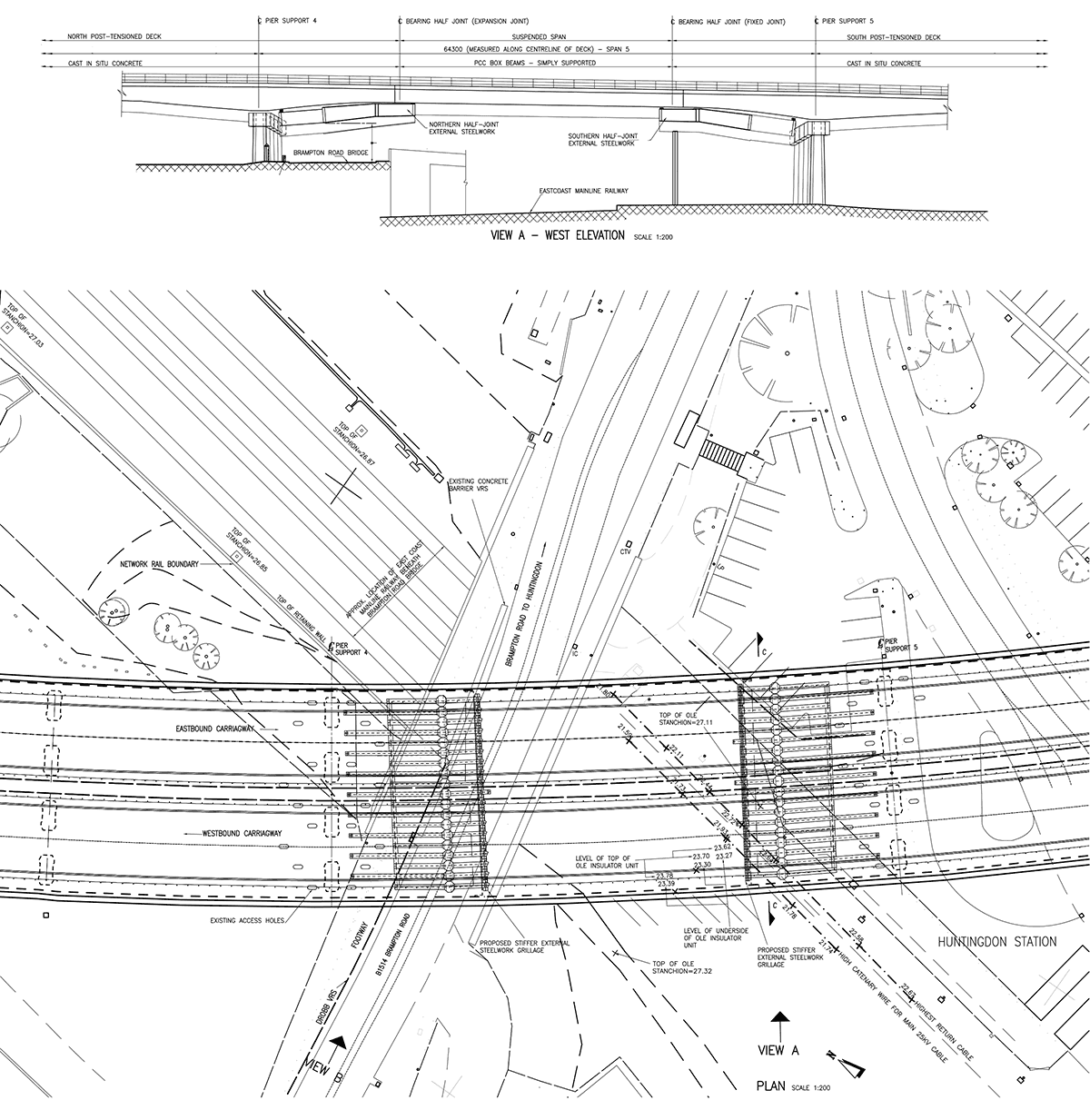
West Elevation diagram
The new scheme will provide a stiffer and longer lasting structure with a series of replacement steel beams located in the same position as the steelwork installed in 2003.
“The new beams are sufficiently stiff that, following some initial jacking in of load, they will radically reduce the risk of half-joint failure as they provide an alternative load path of greater strength and stiffness,” explains Mr Hatcher. “In the event of a half-joint failure, the replacement beams are stiff enough to limit deflection and keep the viaduct serviceable while it’s in operation.
Furthermore, by coupling detailed studies into the vehicular use of Brampton Road with structural analysis techniques, we have been able to achieve this with only a marginal headroom restriction; keeping the route open to all scheduled double-decker buses.”
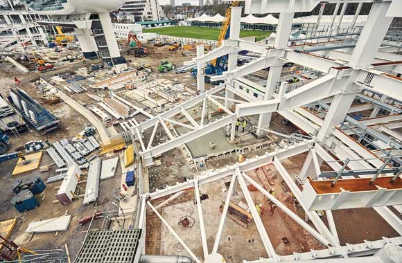
The new steel consists of 38 steel I-beams 1.75m deep and arranged in a grillage formation with 19 members on each side of the viaduct. These deeper I-beams are more durable and inherently stiffer than the original box sections, and are able to provide the viaduct with a sufficiently stiff alternative load path to the half-joints without any significant increase in overall weight.
Main contractor Costain and Steelwork contractor Cleveland Bridge divided the steel installation into two distinct programmes (see box). For the north side of the structure Self Propelled Modular Transporters (SPMTs) were employed to lift and dismantle pairs of steel beams, while on the south side of the viaduct, a large capacity forklift was used as access for the SPMTs was restricted by the rail lines and associated overhead electricity cables.
Apart from a handful of overnight disruptive rail possessions, the work on Huntingdon Viaduct has caused minimal disruption to rail passengers on the East Coast Main Line. The project has also been completed with no disruption to motorists using the A14 as Costain and URS were able to mitigate the need for any traffic management on this key strategic route early in the project.
Steelwork has been beneficial to the project as it is partially assembled offsite to facilitate quicker installation. Cleveland Bridge estimates the average time taken to dismantle one pair of beams and install two new ones was about five hours.
“This is a technically challenging project, however we continue to deliver it safely having not had a lost time accident and expect to deliver it ahead of the contract completion date and within the Client’s budget” says Sean Ellison, Costain Senior Site Agent.
Work on the viaduct is scheduled to be completed later this month (November).
Steel erection programmes
The 38 new I-beams were all installed in braced pairs, with each pair weighing up to 25t.
“As we were reusing most of the existing Macalloys we unbolted and dismantled a pair of box sections at a time, and in the same shift replaced these with a pair of I-beams,” says Ben Binden, Cleveland Bridge Project Manager.
Because some of the beams span live railway lines or a busy road, all of the beam replacement works were done overnight; with many of the lifts requiring railway possessions, with the railway shut to all rail traffic for a maximum of six hours.
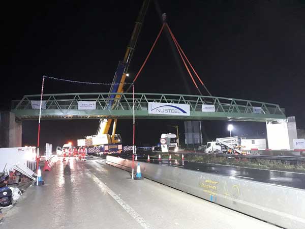
For the 19 beams on the north side of the viaduct, Cleveland Bridge assembled and braced each pair at a nearby assembly point.
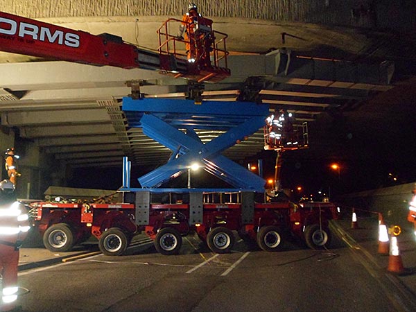
They were lifted onto a large capacity scissor platform attached to an SPMT (above) which was then driven into place under the viaduct. Once the SPMT was in the correct location the beams were then lifted up 5m by the scissor platform and erectors working from adjacent mobile elevating work platforms were able to install them on the Macalloy bars.
However, for the south side of the viaduct, SPMTs could not access the site due to the railway and the maximum lift height increasing to 11m. A large 37t capacity forklift fitted with a 5m high frame was used to lift these beams.
Steelwork strengthening in 2003
Work undertaken in 2003 to the original concrete structure comprised the installation of steel beams inter connected into a grillage attached below the bridge soffits of the two central spans at the half joints.
The steelwork consisted of box sections 800mm deep, 450mm wide and up to 15m long.
The grillages were supported via Macalloy bar hangers, connected to the hollow concrete bridge deck by large diameter pins and internal transfer steelwork.
The new steelwork has also been installed in a grillage formation, matching the steel from 2003 and reusing many of the supporting Macolloy bars. “When the new scheme was being devised all of the bars were discovered to be in good condition and consequently we optimised the design to re-use the existing bars wherever possible,” says Mark Hatcher.