Projects and Features
Rebuild, remodel
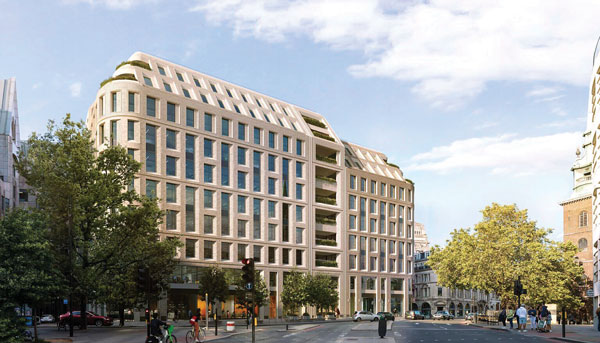
100 Liverpool Street occupies a plot directly opposite the City’s main rail terminus
One of the first phases of the wider Broadgate redevelopment, the 100 Liverpool Street project will link together two existing buildings and add four extra floors to the overall new structure. Martin Cooper reports.
FACT FILE
100 Liverpool Street, London
Main client: British Land
Architect: Hopkins Architects
Main contractor: Sir Robert McAlpine
Structural engineer: AKT II
Steelwork contractor: William Hare
Steel tonnage: 6,000tConstruction projects in the City of London invariably have to contend with a host of challenges, notably the congested nature of the square mile above ground and the myriad of infrastructure that can be encountered below ground.
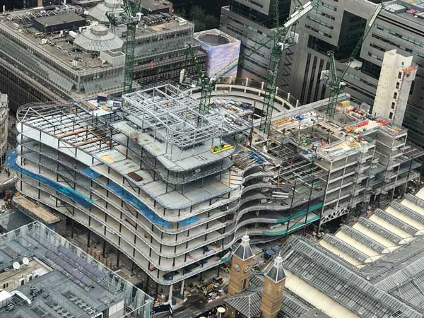
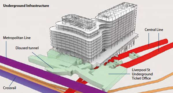
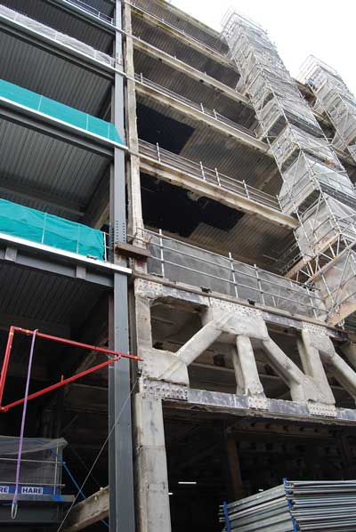
100 Liverpool Street, which forms an initial phase of the City’s Broadgate redevelopment, is a case in point as this site is situated adjacent to one of the nation’s busiest railway stations – Liverpool Street Station – with the terminus’s west entrance even passing through the site along with a shopping mall.
Below ground a mass of infrastructure, including a Central Line tunnel, a disused Victorian tunnel, various access routes and substations are all present.
 The project consists of two existing buildings, 100 Liverpool Street and 8-12 Broadgate, which are being reconfigured into a single structure. All of the substructure is being retained as well as approximately 50% of the original steel frames that extend up to eight-storeys high.
New steelwork is being erected to knit the structures together, replace the demolished areas and add four new floors to the top, creating a new 12-storey landmark building.
“All of the project’s constraints required careful consideration, and drove the project’s design,” explains Sir Robert McAlpine Project Manager Peter Watts.
“The biggest constraint however, was the fact that we couldn’t gain access to the existing foundations because ground floor retail units and the mall have to remain open throughout our programme.”
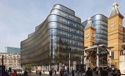
How the completed scheme will look
New composite flooring abutting existing flooring
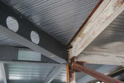
Some existing columns have new steel beams connected to them
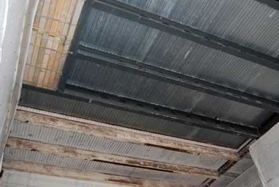
One of the retained trusses that form the bus depot
Sustainability is also at the core of this design, as only steel construction would have allowed the project to reuse the foundations, and then strengthen retained steelwork to allow them to support new lightweight steel floors.
The mall and the west entrance to the railway station also played a significant role in determining when the project kicked-off. Initially a start date at the end beginning of 2017 was penciled in by the team, however with a Christmas closure of the entrance and its shops organised during the festive season, the programme started two weeks early.
Taking advantage of the lull in passenger numbers coming into the City, Sir Robert McAlpine was able to partition the mall and begin the minor demolition works which would allow the steelwork erection programme to begin. Although the mall has remained open, access routes have been moved to allow work to continue, with most work involving the installation of large beams being carried out overnight.
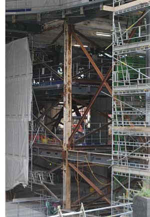
The existing steel-framed buildings were built in the 1980s by main contractor Bovis, with the steelwork contract being undertaken by Redpath Dorman Long. The records of this construction programme and its structural design were readily available and proved to be invaluable when AKT II needed to carefully analyse the structure.
“Analysis of the structure allowed us to identify and utilise redundancies in the original design, and work out which areas of the retained steel frames would need strengthening,” explains AKT II Technical Director David Watson.
“The lightweight nature of a new steel composite design, using Fabsec cellular beams means we have been able to reuse the foundations and only had to strengthen 33% of the existing columns to support the new build elements.”
New steel columns are bolted to the existing steel frame where possible, and the building follows the original structural grid, based around a 7.5m × 7.5m column spacing.
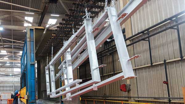
Adding some architectural interest to the new steelwork, fabricated steel transfer beams have been installed to enable set-backs on the new upper levels. These set-backs occur at level eight and 12 on the southern elevation and on level 12 along the northern façade.
Tying in a new steel frame to an existing 1980s frame has been done as seamlessly as possible. Floor slab thicknesses vary throughout the scheme, but in areas where new build meets retained structure, the new slab corresponds to the old.
In the old building, services were accommodated below the steel beams, but as the new areas have cellular beams, allowing the services to be placed within the steelwork’s depth, there are areas where the services transfer from one configuration to another.
The one exception to the standard 7.5m grid pattern is the eastern elevation of the building that spans over the Liverpool Street Bus Station, which has been closed temporarily during the construction works.
Here a series of 15m-long × 2.9m-deep trusses, positioned at level two, have been retained as part of the new design as they create the column-free space for the buses.
Above the bus station, the original structure has been retained up to level seven, with new steelwork added to the top to form the 12-storey new building. Above the trusses the grid reverts back to the 7.5m × 7.5m pattern, with a series of columns supported on the trusses at mid-span. However, from level eight upwards the new floor levels incorporate a 15m span, avoiding additional load on the trusses, while also providing more open office space on the higher levels.
A new steelwork grillage has been installed on top of these bus station trusses and a new floor will be hung from them. This new office level will be within the depth of the trusses in order to maintain the necessary headroom in the bus station.
Explaining the unconventional process, William Hare Project Manager Ivo Garcia says: “Our new steel above the slab connects to the retained steelwork underneath the slab via a series of threaded rods that go through the slab, connecting to the top portion of the retained beam.
“We have to cut the bottom half of the retained UB, transforming the retained section into a tee hung from the above new structure, and effectively transferring the load from the below retained structure to the top structure. This arrangement allows us to maintain the top flanges of the retained beams that include shear studs. After this load transfer operation is undertaken, we then have a series of 200 × 100 RHSs hung from the web of the newly formed tee to support the new hanging floor.”
100 Liverpool Street is due to complete in January 2020.
 Strengthening existing steelwork
David Brown of the SCI offers some pointers
Only a third of the existing columns had to be strengthened during the redevelopment of 100 Liverpool Street – demonstrating the lightweight nature of steel construction, but also showing that strengthening is relatively straightforward with steel members. Column strengthening is usually achieved by attaching plates or other sections to the existing column – generally by welding. The additional steelwork may be attached to the outside of the flanges, maintaining a ‘H’ cross section, or across the tips of the flanges, creating a box section. The latter option may be preferred if minor axis buckling is the critical design check.
Generally, it is difficult to de-stress the columns, so the strengthening works are completed whilst the existing column is at least partially loaded – though usually much less than the original design load. Assuming that flexural buckling is critical, it is conservative to calculate the buckling stresses in the existing section under the temporary load and add them to the stresses within the compound section caused by increasing the temporary load to the final design value.
The stress in the original section can be determined by assuming an elastic stress distribution based on:
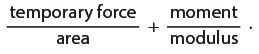
The moment depends on the initial eccentricity, amplified due to the axial load. The initial eccentricity should be back-calculated from the original design resistance of the section, and then amplified due to the temporary force to determine the moment to be considered in the temporary case. More details of the process are given in reference 1.
The stress distribution in the compound section should be based on the increase in load from the temporary state to the final design value, although the initial imperfection should be amplified based on the final design value, not the increase in load. The cross sectional area and inertia will have increased, and the slenderness will decrease compared to the original section. Generally it is good practice to ensure that reinforcing elements do not suffer reductions in resistance due to local buckling, so are Class 1 or Class 2. The two stress diagrams can be superimposed and the cross section checked to see if any point exceeds the yield strength. Although flexural buckling is likely to be critical, the cross section may need verification, particularly at connection locations where it may be difficult to reinforce the cross section.
The reinforced section must behave as a compound section, so welding the reinforcing plates or sections is usual. Appropriate welding procedures will be required for the materials, thickness, welding process and welding position.
1. Member imperfections, September 2011, New Steel Construction