Projects and Features
Portsmouth Spinnaker Tower
The Spinnaker Tower will be the tallest publicly accessible building in the UK outside London. It is certainly one of the most exciting structures in Britain and is set to become a world-famous icon for structural engineering.

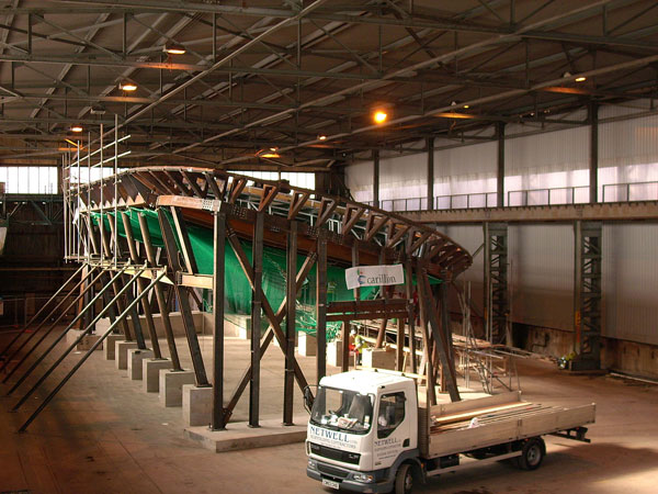
Fig. 3. Construction at March 2004. (Photo: J. Tubman)
PROJECT
Title Portsmouth Spinnaker Tower
Location Portsmouth, England
.
TEAM
Client Portsmouth City Council
Principal Contractor Mowlem
Structural Engineer and Lead Consultant Scott Wilson
Architect HDL Partnership
Steelwork Contractor Butterley
.
COST
Project value £23m
Steelwork tonnage Approximately 1,400 tonnes in primary elements excluding base building.
.
TECHNICAL
Design Code BS 5400
Structural Analysis package ABAQUS
Grade and subgrade of steel S355J2G3 or equivalent for all primary elements of tower superstructure
.
CORROSION PROTECTION SPECIFICATION
External steelworkacrylic polysiloxane top coat over high solids zinc rich primer
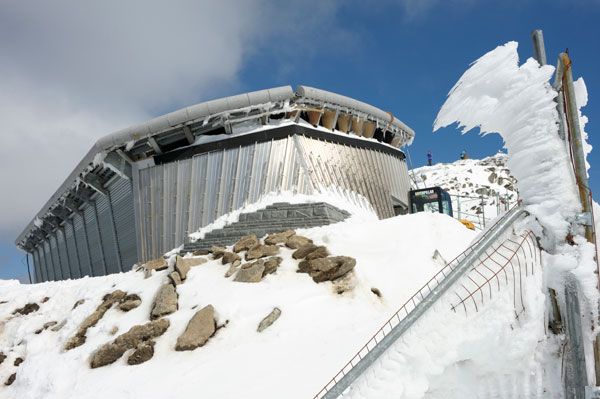
Located on the eastern perimeter of Portsmouth’s historic naval and commercial harbour on the south coast of England, the curves of the Spinnaker Tower (fig. 1) are taking shape as the structure rises towards its full height of 170m above sea level.
Being constructed under a design-and-build contract awarded by Portsmouth City Council to Mowlem, the tower forms the centrepiece of much wider regeneration works for the harbour. The construction cost of approximately £23m is being funded jointly by the Millennium Commission and Portsmouth City Council.
The Spinnaker Tower serves a number of functions: as an icon for the city of Portsmouth; as a shining white beacon on the south coast for ferries and naval vessels as they return to port; as a spectacular waterfront sculpture; and as perhaps the most impressive and most interesting observation platform in the UK.
Three viewing decks at about 110m above sea level will provide views of up to 23 miles over the Solent, the Isle of Wight, the harbour and the coast to the east and west. Visitors will be transported to the viewing decks by either an internal high-speed lift or an external panoramic lift. The upper deck will be open to the wind for the more adventurous visitor.

Fig. 1. Spinnaker Tower – artist’s impression
SCOTT WILSON’S ROLE
Scott Wilson’s role started at the time of concept design in 1999, at that time working with their partners in the preliminary engineering to define the final shape of the structure and approximate member dimensions, and to contribute to the employer’s requirements for the construction contract. Scott Wilson was then employed as independent checker for the substructure design and as lead consultant and structural engineer for all of the superstructure design.
STRUCTURE
The tower stands in the water and, structurally, is independent of the adjacent Gunwharf Quay development, though a transition slab permits pedestrian and emergency vehicle access from the Gunwharf slab to the tower slab. It is located on a postage-stamp sized site. The size and location of the site and the very unusual shape of the structure combined to pose some very interesting design challenges.
Design, detailing and specification have all had to reflect the structure’s unique marine environment. Health-and-safety issues have received careful attention at all stages of the design and construction process and, inter alia, have addressed safety in long-term maintenance operations. Materials selection (including paint, etc.) has also played a significant role in trying to minimise the need for future maintenance operations at height.

Fig. 2. Principal elements of structure.
The main structure (fig. 2) comprises a piled foundation supporting a concrete raft, a reinforced concrete slipformed A-frame (two hexagonal section “shafts” merging at 76m above sea level) rising to 143m above sea level, a 27m-high composite spire to crown the A-frame and two very large, variable depth, curved, steel box girders which form the “bows”. The bows spring from their raft base at the back of the structure, rise to intersect between the legs of the A-frame at approximately 35m above sea level (the level of the so-called “trunnion axis”), pass through to the front (the south side) of the structure and continue to rise, billowing out towards the sea as they do so in the large spinnaker curve which gives the structure its name. At their upper ends, the bows connect back into the concrete shaft at a level of approximately 119m above sea level. Between the box girders and at the front of the structure, the impression of continuity of the material of the spinnaker sail is provided by a series of curved, horizontal, inverted aerofoil section steel “ribs”. A series of pin-ended, horizontal, tubular steel “spacers” connects the steel bows back to the concrete shafts at intervals up the height of the structure. These spacers transfer forces in both the temporary and permanent conditions.
BS 5400 was used as the principal design code. This was particularly necessary for the steelwork where the complexity of the large curved box girders forming the spinnaker “bows” could not have been addressed satisfactorily by BS 5950, the design code for steel buildings.
Access to the site is constrained by a pinch point just outside the site boundary. The design had to allow for transportation and erection of bite-size chunks of steelwork of a size commensurate with this access constraint and of a weight capable of being lifted by the tower crane used for erection of the upper sections of the bows. The lower 560 tonnes of steelwork in the bows and trunnion was brought to site in sections, TCB bolted together and strand-jacked into position in early March 2004 (fig. 3). Much of the design was dictated by the construction condition and pre-cambering of all primary elements (including the slipformed concrete shafts) was necessary.

Fig. 4. Bow element. (Photo: P. Papathanasiou)

Fig. 5. Intersection of the bows at the Trunnion axis location. (Photo: P. Papathanasiou)

Fig. 6. Rib member. (Photo: P. Papathanasiou)
The articulation scheme for the structure was a crucial part of the design. Four different articulation options were kept open for as long as possible in the design process. The scheme finally adopted sees the steel box girder bows bolted down to the concrete raft to form a moment connection at their base. Vertical support to the steel bows is also provided at trunnion level (where the bows intersect the concrete A-frame) but care has been taken to ensure that relative rotation between bows and shafts is possible here. This is effected by the use of two large spherical bridge bearings, one at either end of the trunnion member. Where the bows return to the shaft at the top of the structure, articulation is provided by small bearings providing small amounts of vertical support and permitting rotational freedom between the steel bows and concrete A-frame. All primary steelwork in the superstructure is grade S355J2G3 or equivalent and the bows, trunnion, ribs and spacers together account for approximately 1,200 tonnes of fabricated steelwork. The box sections of the bows (fig. 4) are 1,500mm wide throughout and vary in depth from 2,000mm to 7,400mm with flange thicknesses of 20 to 30mm and web thicknesses of 18 to 50mm. The trunnion is a short but key, highly stressed box girder 1,650mm wide and 2,000mm deep (fig. 5). The spacers are 660mm diameter pin-ended steel tubes. The ribs (fig. 6) vary in length from 16m to 23m and comprise two curved tubes of different diameter with flat plates top and bottom to form the desired aerofoil shape.
MARINE ASPECTS
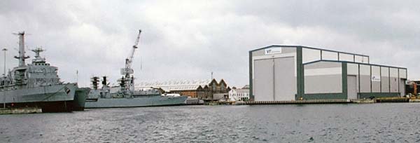
Its location in the water of one of the busiest harbours in the UK meant that the risk of ship impact had to be addressed in the design. This was achieved by the provision of an independent, piled, ship impact structure in front of the main tower raft. In plan, the ship impact structure is curved to complement and complete the curved shape of the main raft and is not readily identifiable by the public as an independent structure. The impact energy of colliding ships of moderate size and speed would be absorbed by flexure of the impact structure’s fifteen piles without detriment to the tower.
In general, piles are founded between about 32m and 47m below Ordnance Datum, are of bored construction and their 1,350mm diameter steel casings extend to approximately 18m below raft level. The concrete raft forming the base of the tower is of conventional in-situ reinforced concrete construction on non-participating, sacrificial, precast concrete permanent formwork over the greater part of its plan area. There are over 70 piles supporting the main raft.
WIND LOADING
In addition to its proximity to naval and commercial shipping lanes in the harbour and the implications of this in relation to possible ship impact, the structure stands in a very exposed position from the point of view of wind loading and bears the full force of strong south-westerly winds from the Solent. A significant proportion of the loading on the structure in both its construction and in-service conditions arises from the wind. The overall shape of the structure and the shapes and dimensions of some of its constituent elements meant that wind tunnel testing was essential for a thorough understanding and quantification of static and dynamic wind loads.
The results of the wind tunnel tests were used not only in the “static” design of the structure but also to determine the dynamic response of the structure overall, the aerodynamic stability and fatigue characteristics of individual elements and, crucially, the likely human response to windinduced movements of the Tower at viewing deck level to ensure visitor comfort.
PROGRESS
Steelwork erection is well under way and completion of the structure is scheduled for the winter of 2004/5.
Dr. John Tubman, Director, Structures and Advanced Technology, Scott Wilson.
Mr. David Webb, Principal Engineer, Scott Wilson.
Dr. Duncan Lillistone, Senior Engineer, Scott Wilson.