Projects and Features
Plymouth University Extensions at Portland Square
Plymouth University has recently opened a major extension to house several departments.
Project team
Client University of Plymouth
Architect Feilden Clegg Bradley Architects
Structural engineer Buro Happold
Main contractor Bovis Lend Lease
Steelwork contractor Rowecord Engineering
IN August 2003 a brand new faculty building for the University of Plymouth was opened by the Rt. Hon. Lord David Owen, providing some 12,000m² of lecture theatres and offices. The project was commissioned in 2000 in order to provide a home for the Peninsular Medical School and various science and computing departments. Following a limited architectural competition, Bath-based Feilden Clegg Bradley Architects was chosen to carry out the design, with Buro Happold providing civil, structural, building services and fire engineering advice. Davis Langdon Everest from Plymouth was appointed as the cost consultant.
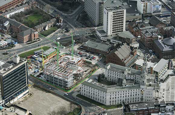
THE SITE
The site was occupied by a number of terraced houses, a car park and squash courts belonging to the University and is bounded to the west by Portland Road and to the east by the recently developed Sherwell centre, a converted church. The site slopes relatively steeply toward the south and is underlain by slate. A number of architectural studies were carried out to establish the optimum configuration, which proved to be three interlinked blocks that are five storeys high at the top of the site, with an additional storey being added as the buildings terrace down the site. Each building is arranged in a U-shape around a full height atrium. The form of the building was driven in part by the environmental strategy, which utilises night-time cooling of pre-cast concrete hollowcore slabs, with the air being drawn from the facades using the stack effect generated in the atrium.
THE BRIEF
A fast programme and the architects’ desire to avoid downstand beams led the engineers to adopt a structural steel frame solution which incorporates a number of interesting features. The most obvious of these, clearly visible as you enter the atria, are the three primary frames stabilising the buildings in the north-south direction. The desire to maintain clear uninterrupted curtain walled elevations meant there were very few locations where conventional cross bracing could be used. In the east-west direction it was possible to find two locations in each building, adjacent to toilets, where solid external walls could hide the presence of bracing, but a suitable location for the north-south system could not be found. The engineers suggested that with sufficient size, a single portal frame could be located within the atrium of each block, which would provide the required stiffness. This worked well with the strategy for dealing with the building movements, as a movement joint was to be located between each of the three blocks.

Fig.1. Main stability frame and hanging stair at the rear of the Building B atrium.
Fig. 2. Detail of splice connection in main stability frame showing 56mm diameter bolts.
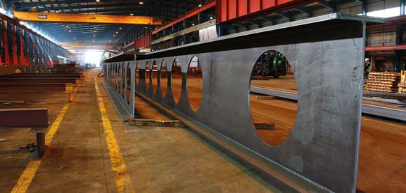
STRUCTURE
The portal frames vary significantly in their form as they rise through the building, with the columns being fabricated plate steel for the lower two floors and rolled sections above. The lower section columns are 1300mm wide with flanges made of 450mm x 50mm plates and 20mm webs (fig 1). Initially the webs of the columns were to have been stiffened horizontally, but it was decided that this would have been too much of a temptation for the students, who may have wished to show off their climbing skills (or lack thereof) up the resulting ladders. Within the lower two storeys, the portal frames are joined at the midpoint of the horizontal member. Although significant bending is still to be found at this point due to the applied loading from the floors, the joint is configured to represent the theoretical point of contraflecture found in a horizontally loaded frame. Both the architects and the engineers were convinced that the classical method for connection of multiple small bolts would not give the required result, so the engineers proposed that six 56mm diameter bolts be used in a plate stiffened connection (fig 2).
This location also allowed the fabricator to bring the two halves of the frame together on site with a simple, if not potent, bolted connection. Because the vertical members of the frames within the atrium are located away from the walls, buckling restraint of the columns is provided by the horizontal members. These continue to the floor plates and are linked into the stability system in the east-west direction through a reinforced concrete topping located on top of and acting compositely with the precast concrete floors.
High bearing pressures were capable in the underlying slate and it was considered economic to use spread footings wherever possible. However, these would become large if the moments from the portal frames were taken into consideration. It was decided that a bearing would be incorporated at the base of each leg. Ekspan 30K0350 bearings were selected, capable of carrying the 4700kN vertical load whilst providing adequate rotational capacity.

Fig. 3. Typical floor edge detail allowing
minimum structural depth
The ambition, mentioned earlier, to keep the glazed elevations as open as possible meant that downstand beams were not desirable around the building perimeter. Since the environmental strategy passes air through the hollowcore planks at right angles to the perimeter beam, they carry significant loading from the floors, which span up to 10.5m. In addition, the overall beam depth was limited so as not to close off the raised floor void which is used as the air path at the perimeter. In order to achieve this, a perimeter column spacing of 5.4m was chosen, with the perimeter beams being 400 x 200 RHS sections capable of resisting the torsional moment from the plank support. A 15mm steel plate welded to the underside of the RHS sections supports the precast concrete planks (fig 3). End plate connections between the beams and columns were to be exposed in the final condition, and a collaboration between the architects, engineers and fabricators allowed a detail to be evolved which solved all of the visual, strength and constructability issues. Disproportionate collapse had to be considered due to the building size, and the designers opted for key element approach to satisfy the Building Regulations requirements.
CONSTRUCTION
The project was let under a two-stage modified JCT form of contract with Bovis Lend Lease as main contractors. The contract for the structural steel frame was won by Rowecord Engineering, with the pre-cast planks supplied by Bison under a contract novated to Rowecord to ensure that the erection of the frame was carried out effectively under a single subcontract. Rowecord’s engineers played an active and progressive role in the development of the design. This included the addition of temporary plan bracing laid on top of the pre-cast planks, allowing the building to reach its full height without the need to cast the in-situ concrete toppings which would have delayed progress on site. Rowecord also brought its experience to bear in the design of the columns splices in order to minimise their visual impact.

Fig. 4. Stair hanger bifurcation detail

Fig 5 Stair hanger details showing typical connection with flight and bifurcation above
The central atria also contain a feature accommodation stair supported from both the cantilevered walkway in front of the portal frames and from a single steel hanger which bifurcates above the upper half landing, connecting into the columns at roof level (fig 4). The hanger, a 36mm steel rod, supports four flights of stairs and is connected to the stair flights using a detail which allowed for the levelling of the flights and a pin detail to avoid overstressing of the steel bar. Again, this detail was developed with the Rowecord engineers to satisfy the aesthetic and functional requirements (fig 5). Of particular concern to the engineers was the dynamic behaviour of the stair structures.
OTHER DESIGN CONSTRAINTS
Buro Happold has been involved in the design of long span and light structures for many years and, through its work on sports stadia, has broad experience of the dynamic behaviour of crowds. All of this was brought to bear on this project, and a full dynamic model of the structure was made. Because this structure is very light and has very little natural damping, the natural frequencies of the structure had to be chosen to ensure that reinforcement from footfall did not occur. A target natural frequency of 6Hz was chosen.
Interestingly, the most significant dynamic modes were not derived from the behaviour of the hanger but from what were thought initially to be secondary effects. These included minor axis bending in the supporting channel at the front of the balcony walkway attached to the portal frames to which the stair flights were attached.
Due to programme constraints, the structural frame was procured and the fabrication drawings were in production by the time the curtain walling subcontractor, Mero, was appointed. Although at a late stage, it was decided it would be beneficial to the project for the design team, including Rowecord and Mero, to incorporate the necessary cladding fixing details into the Rowecord package. The design development was carried out at great speed, but the necessary details were delivered to site fixed to the main structural elements, thus avoided the potentially laborious on-site fixing of the curtain walling brackets which would have been made more difficult by the use of the perimeter RHS sections.
In addition to advising the architect on escape strategies, Buro Happold’s fire engineering consultancy (FEDRA) also carried out fire simulation modelling in different areas of the building. This information was used to make individual assessments of the primary steel elements, allowing the intumescent protection to be reduced or removed where not required.
Steve Fisher MIStruct, C.Eng, senior associate at Buro Happold and Austen Cook M.Eng, Structural engineer at Buro Happold