Projects and Features
Modern Roof Cladding Systems
Recent changes to Part L of the Building Regulations mean that it is now more important than ever for designers to understand how the various components that make up a roof cladding system interact to carry the applied loads and form part of an airtight building envelope.
There is concern in some parts of the industry that the current generation of purlin and cladding products used to construct building envelopes are not being properly specified and/or constructed.
This concern relates to a potential over-reliance on previous experience when, for various reasons and in particular regulatory changes, envelope construction has changed significantly.
The following issues have been highlighted by the Steering Group of a Steel Construction Institute ‘Partners in Innovation’ project as being of particular importance:
- Lack of consideration/understanding of loads and load paths;
- Interaction between the components forming the roof system;
- Tolerances that affect the positions of the purlins.
DESIGN
Load paths To achieve safe construction, the way in which components act together, the loads to which they are subjected, and how these loads are transmitted must be understood.
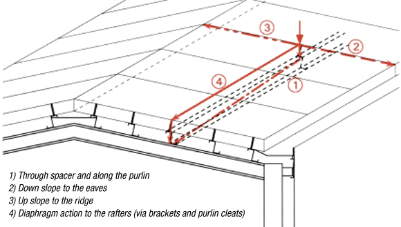
In particular, designers need to consider how the down-slope loads applied to the outer sheets of built-up roof systems are transferred back to the main frame. There are potentially four load paths as shown in Figure 1. The load will be shared between these paths in accordance with their relative stiffnesses (rather than simply the assumptions of the designer):
- Through the spacer brackets to the purlins, then back to the rafters;
- Through the outer sheet down the slope to the eaves;
- Through the outer sheet up the slope to the apex;
- In diaphragm action through the outer sheet, and then via the spacer brackets, to the rafters.
Understanding the load paths in built-up systems has become a particularly important issue following the 2002 revision of Part L of the Building Regulations, since this revision has resulted in significantly deeper rail and bracket systems to accommodate an increased thickness of insulation. The reduction in the stiffness of rail and bracket systems will result in a smaller (possibly negligible but certainly in need of consideration) proportion of the down-slope load taking load path 1, but whatever load there is will now combine with a substantial lever arm and therefore have the potential to manifest itself as a reasonable overturning moment at the base of the brackets. If load path 4 is to take the majority of the loading then the brackets over the rafters must be sufficiently stiff to attract that loading, and sufficiently strong to transfer it. Whatever the detailing, there is a need to verify the viability of the load path(s), as the assumptions on which roof design have traditionally been based may no longer be valid. The various components that make up the roof system should all be designed and detailed to enable the down-slope loads to be transferred safely from the outer sheet through to the primary steelwork (e.g. rafters).
Interaction of components
Efficient and safe design relies on interaction between the purlins and cladding. This interaction will require in-plane and flexural stiffness from the cladding and tensile, shear and (potentially) moment resistance from the fasteners. Restraint is normally required to ensure that the purlins are adequate to support the loads applied during the construction and final conditions. The purlins have traditionally been sized utilising this interaction, and chosen from manufacturer’s information to carry the necessary loads over the required span on the assumption that they will be fully restrained. The justification for purlin size is therefore based on tests undertaken by the manufacturer with adequate restraint present. However, designers should consider carefully what sheeting and fixings will be used and content themselves that this will be adequate (referring to the manufacturers for information if necessary). Simply relying on past experience, which was established when insulation thicknesses were considerably lower than today’s values, is not recommended. Specifiers should be aware that if the cladding and/or fixings are not able to provide the necessary lateral and torsional restraint, the purlins will be undersized.
It should also be understood that there are various restraint requirements covering the construction condition, and the final condition with either uplift or down loads. The level and type of restraint will vary depending on the conditions, some of which cause compression in the upper flange and others the lower purlin flange.
CONSTRUCTION
Position of purlin flange
In order to allow easy and correct fixing of the cladding, the purlins must be sufficiently close to their nominal positions at the time of cladding installation. Two problems have been identified:
- Deviations in the position of the primary steelwork affecting the positions of the purlins at their supports.
- Deviations within the span of the purlins (within or orthogonal to the roof plane).
The provision of a lap between the liner sheets in built-up roof systems means that ‘reasonable’ deviations can be accommodated. The lack of a lap in composite panels, together with bearing requirements and manufacturing tolerances associated with panel length, mean that considerably greater care is needed to facilitate fixing of the panels to the purlins and provide adequate bearing. Out-of-plane purlin deflections can also cause problems, because the rigidity of composite panels may result in a gap between the underside of the panel and the top of the purlin. This may cause difficulties fixing the cladding, especially when fixings of insufficient length are specified. In the past, most installation problems have been overcome on site by the roofing contractor, but changes to the rules to satisfy the revised (2002) Part L requirements for airtightness of buildings mean that greater care is needed to ensure a quality product.
To avoid excessive purlin deflections, the construction loads carried by the purlins and the restraint provided by the cladding at different stages in the construction process must both be considered by the designer. On site, careful thought should be given to the construction sequence to ensure that the designer’s assumptions regarding loading and restraint are realised.
WHAT TO DO?
The issues identified in this article are one of the first outcomes of an SCI project (funded by the DTI, the MCRMA and Corus) that has comprehensive input from all interested parties. The project will lead to best practice guidance for both designers/specifiers and site practitioners, recognising that the issues can be addressed using current products provided there is an improved level of understanding throughout the industry. Prior to the publication of this formal guidance designers and site practitioners should be aware that:
• There is nothing inherently wrong or unsafe with either built-up or composite metal cladding systems, however,
• The designer or specifier should carefully consider how chosen components will be built, act together, and carry the applied loads back to the primary structure
• Site practitioners should be made aware of the assumptions that have been made by the designer, as even the most capable products become incapable if not used correctly.
Dr. Graham Couchman, Senior Manager, and Dr. Martin Heywood, Principal Engineer, SCI

