Projects and Features
Hungerford Bridge Walkways

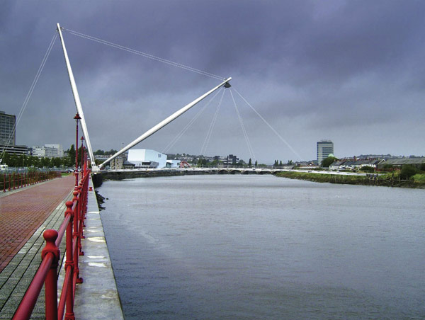
London’s Hungerford Railway Bridge has had twin walkways installed on either side (Photography by: Duncan Lawson)
Twin walkways to either side of London’s Hungerford Railway Bridge have visually enhanced the link across the river and provided pedestrians with stunning views of the Thames and the Houses of Parliament. David Dibb-Fuller reports.
FACT FILE: Hungerford Railway Bridge pedestrian walkways
Architect: Lifschutz Davidson
Structural engineers: WSP Group with Gifford & Partners
Steelwork contractor: Butterley
One of the least popular Thames crossings has been transformed by the construction of twin cable-stayed pedestrian walkways on either side of Hungerford Railway Bridge, linking Charing Cross and the South Bank Centre. Complex and innovative engineering has been required from the construction team, not least because of a redesign after the design-andbuild contract had already been let.
To each side of the 350m long railway bridge a 4m wide walkway has been added, comprising a slender concrete deck suspended by steel cables fanning out from a series of six inclined pylons. The decks are not connected to the rail bridge but supported by the pylons which are founded on concrete piles extending some 40m into the river bed.
Multi-span cable-stayed structures are very complex to analyse, and design of the Hungerford footbridges was made more complicated by alterations to the layout of the pylons brought about by London Underground’s insistence that piling works could potentially detonate World War 2 ordnance buried in the Thames silt, leading to calamitous damage to the nearby Northern and Bakerloo underground lines. So the location of the most northern pylon was moved out of the river and onto the riverbank, involving a late change of foundation and pylon design. The most northerly span was lengthened by 10m, so considerable load was added to the most northerly pylon. The design of the last pylon was raised in height to keep the angle of cables consistent and the whole design was re-analysed to ensure its continued integrity.
History of the site
The first bridge on this site was a pedestrian suspension structure built by Isambard Kingdom Brunel and opened in 1846. When the railway arrived at Charing Cross the masonry supports of Brunel’s bridge became supports for a new railway bridge designed by Sir John Hawkshaw. This new bridge, completed in 1864, had cantilevered walkways on either side, but the upstream walkway was demolished in the 1870’s when the bridge was widened. In 1951 the Royal Engineers created an upstream walkway for temporary use during the Festival of Britain by adding a Bailey bridge.
Original design for new walkways
 By the 1990’s Hungerford Bridge’s remaining walkway had become less and less used by pedestrians. The Cross River Partnership, a public and private sector group which promotes cross-Thames links, organised a design competition which attracted over 40 entrants. The winning design came from a team comprising engineers WSP Group, architects Lifschutz Davidson and cost consultants Davis Langdon and Everest. Their proposal was for twin cable-stayed bridges, one on either side of the existing bridge. The design also included low-level link bridges from the South Bank to Brunel’s south pier – the Surrey pier – and boat landings. The winning design was praised by the judges for showing respect to the historical context as the new spans matched the old, and the important parts of the existing structure were emphasised.
The pre-tender design was a multi-span cablestayed bridge with short spans of some 50m supported by Macalloy bar stays, chosen for aesthetic reasons. To minimise the size of each bar a large number of stays – 28 – were provided for each pylon. The pylons were tapered steel cylinders held by additional Macalloy bars and supported on concrete foundations. At the south bank pier each deck was supported from a pair of pylons founded on a new island. This design feature was to help focus attention on the old structure and permit a staircase to run from the walkways to the island. From here a walkway would pass through Brunel’s original structure and steel footbridges would join the island to the south bank.
Alternative design options
Within weeks of the award of the construction contract to a Costain and Norwest Holst joint venture London Underground raised the issue of possible damage from unexploded bombs. One option would have been to close the tunnel floodgates during piling works and until after a time-delay fuse would have activated. But this would have meant shutting the underground lines for four days. Gifford was commissioned to investigate other options and recommended a revised design eliminating the risk from piling. The solution was to move the foundation for the north pylon out of the river. This meant that the originally proposed asymmetric pylon could not be employed, so an A-frame solution was adopted. The adjacent foundation to this was further away from the Bakerloo Line, but for safety, it was decided to hand dig a five metre diameter shaft rather than pile. The two link bridges were dropped from the design.

The original contract, based on the Institution of Civil Engineer’s Design-and-Build form, was renegotiated at this stage. A new contract was drawn up based on the NEC Engineering and Construction Contract that allocated design responsibility to the contractor and his designer, Gifford. The client’s engineer remained responsible for design aspects relating to dynamics.
The changes to the foundations on the north bank meant that the whole bridge had to be redesigned at this stage. Gifford had developed the design after tender and produced construction drawings. This was not an easy task as the multi-span cable-stay design had multiple redundancies, with almost every element having a different loaded length.
Gifford amended the original design, incorporating several design innovations. One involved incorporating unobtrusive spherical bearings in the bases of the pylons which made it possible to design the pylons as tapered pinended struts and made erection faster and simpler. Spherical bearings were introduced in the pylon top to relieve global bending effects from temperature, creep and shrinkage.
Sections of flat plate – generally grade S355J2 – which were thicker towards the ends where the radii were smaller – were rolled to conical or cylindrical shapes as required and welded to form the pylons. Billets forming the pylon tip, 150mm thick and made from grade S355NL, had enhanced Charpy energy absorption requirements and improved through-thickness properties. Plates used to connect the Angel wing plates to the top spherical bearings were grade S460NL, also with enhanced Charpy energy absorption requirements.
Three-dimensional finite element modelling optimised the steel section design and minimised the need for complex welded fabrications. Fabricated steel deck connections were replaced by castings stressed onto the concrete at the lower end of the stays. The deck was originally designed to be stressed, with tendons at the neutral axis, but when the span adjacent to the A-frame was lengthened axial pre stress was no longer adequate and draped tendons were needed to deal with the greater sagging moments at mid span. During the incremental launch process this led to stress reversals that meant that temporary external stressing would have been needed. Being able to design the deck in heavily reinforced concrete with the same cross section meant that prestressing was not needed and was removed.
Because of the A-frame support at the northern end a new articulation layout was introduced. Large uplift forces were generated at the northern abutment because of the difference in span lengths on either side of the A-frame, making it impractical to tie down the deck while allowing longitudinal movement, which was allowed by introducing a maintenance-free stainless steel dowelled expansion joint to the south of the A-frame. This also meant rotation was possible, while lateral and vertical movement were resisted. An integral fixed support was provided at the north end. The rest of the bridge was fixed at the Surrey pier by bracing the pylons, and a second expansion joint was provided at the south end, lateral restraint being provided by steel struts between the deck and the backstay nodes. It was important to avoid the new structure creating additional loads on the old structure so gaps were maintained between the two. The ability of the old structure to articulate independently of the new was preserved.
Construction

The main bridge decks were constructed using incremental launching. A casting bed was created on a steel framework in the nonnavigable span adjacent to the south bank where a 50m section of deck was first cast. A temporary stiffening truss was bolted to the top of the deck and hydraulic jacks pulled it northwards. The process was repeated until the entire deck was complete.
A floating crane lifted the pylons into place, each erected with its backstays attached. Deck stays fabricated to pre-set lengths were temporarily supported by strong-backs and installed with a pre-set sag to aid connection of the fork and spade pin anchorages.
Once all deck stays had been installed, the deck was lowered in a controlled sequence until supported entirely by the stays, which were then “tuned” to the correct load by measuring their frequency. Temporary truss and tower supports were then removed.
Opening of the twin walkways in 2002 has added symmetry to the original 1864 bridge’s elegant appearance, as well as providing the capital’s residents and visitors with a dramatically improved crossing which is proving to be a popular tourist attraction in its own right, offering one of the finest views of the Houses of Parliament upstream. Since opening, the crossing has been renamed the Golden Jubilee Bridges and has been named winner in the Specialist category of the Royal Fine Art Commission Building of the Year Award 2003.
Credits
David Dibb-Fuller is a partner at Gifford & Partners Ltd