50 & 20 Years Ago
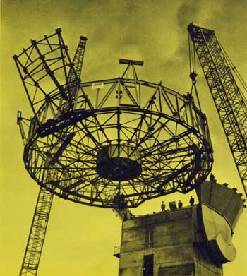
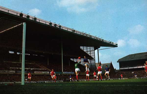
Football Stand for 1966 World Cup Series
 The directors of Manchester United Football Club had for some time been thinking in terms of developing the north side of the ground but it was not until late in 1963 that they instructed their architects to go ahead with a definite scheme.
This was to accommodate 10,500 seats without reducing the capacity of the ground and was achieved by building out over the ground level concourse at the back of the existing terraced bank as far as the boundary wall. As the scheme also included the unique feature of private boxes with rear entrance at the back of the stand and necessitated a cantilever roof it presented a difficult structural problem in the limited space available for counterbalancing the cantilever.
 A Problem Solved
Many structural forms were explored, particular efforts being made to devise a stayed cantilever solution. The lack of space coupled with reversal of forces by wind uplift defeated such a scheme and the form adopted is basically the simplest possible. Various materials of construction were considered and several subjected to cost test by tender. It became very evident that maximum economy would be achieved by choosing the cheapest and lightest satisfactory roof sheeting – 18 gauge long length aluminium trough section – and designing the roof structure around that.
Initially it was felt that sections of tubular steelwork would prove economical and the first truss design was based on them. Tenders showed, however, that the fabrication, erection and protection factors outweighed the saving in material and therefore standard steel sections were used instead, with Universal columns for the top and bottom booms, starred angles for the latticing members and Universal beams for the purlins. Mild steel was adopted in preference to high yield stress steel in order to limit deflections. Welding runs along the main axis have been used for shop connections and high strength friction grip bolts for site fixing. Welds were satisfactorily subjected to radiographic examination. Protection of the steel work was achieved by blast cleaning followed immediately by weldable zinc-rich epoxy priming and later by micaceous iron oxide finishing paint.
The roof decking has been placed at the bottom of the truss for several reasons – compression boom restraint for the natural gravitational condition, internal appearance, easy access for maintaining the majority of the steelwork and natural roof drainage. These outweigh the major disadvantage of leaving most of the steel exposed to the weather. As wind uplift can almost completely reverse the maximum stress distribution the top boom also required buckling restraint. Locally high wind pressure from gusting is spread by the fascia and two inclined transverse stiffening girders. The fascia also breaks up laminar wind flow and reduces air pressure on the roof.
Upstand trusses created a minor problem in sheeting. To hang this below the bottom boom meant either double purlins or a complicated buckling brace and also left flashing difficulties around the hangers. To run the sheeting over the boom presented impossible flashing details around the lattice members. The solution adopted at Old Trafford was to bolt the purlins to the underside of the I boom and run the sheeting under the protective cover of the top flange of the boom. Each bay of sheeting was therefore independent and easily flashed, except at the hinge connection with the concrete columns where a rather complicated capping piece was required.
Changes in Material
The vertical member supporting the cantilever and the raking beam which stabilizes it and carries the upper level of terracing were both initially considered in steel plate girder section. As the steel would have required fire protection it was found to be cheaper to cast them in reinforced concrete. Whatever material ha been adopted there would have remained a difficulty in connecting it to the cantilever (a) because of the solid form of the one and the lattice form of the other and (b) in order to allow adjustments in position in order to level up the trusses.
The change in material simplified the detailing of this connection, particularly as the bending forces in the truss are about six times as great as the shear forces. The bottom boom is hinged the concrete column, allowing easy rotation and a small amount of vertical and horizontal movement, whilst the top boom slots between two pairs of steel channels embedded in the top of the column. The truss was made in two parts, the first being lifted over by tower crane with the hinge completely attached to the truss.
The hinge was bolted on to the column while the crane held the truss and the top boom was temporarily cleated to the back pair of channels. This released the crane to bring over the front half of the truss which was bolted over the back half. Temporary jacking cleats were then fixed to the top boom between the two pairs of channels and twin jacks fitted between these cleats and the front pair of channels. The jacks were simultaneously operated to take the load off the back pair of channels and onto the front, at the same time raising the truss to the correct level. The permanent rear cleats were then fitted, side drilled, packed off the rear channels and friction grip bolted after which the jacks were released and the load re-transferred to the back channels. The jacking cleats were removed and permanent ones fitted between the boom and the front pair of channels. The whole assembly was then encased in concrete. Prior to this capping, the boom loads were transferred to the concrete by the channels working as brackets but, for loads applied after capping, the concrete cap dealt with the bending forces and the channels only had to be designed for the shear forces.
The remainder of the steelwork was bolted into position, the majority being within reach of the tower crane but the fascia and front two purlins being lifted by derrick. Erection proved to be very straightforward and a full scale overload test of one truss demonstrated its behaviour to be as intended.
Credit is due to the main contractor, who worked very efficiently in very limited working space – having to keep as much of the ground open as possible during Manchester United’s successful and well attended 1964/65 season – and to the steelwork sub-contractors. Some 8,000 seats were taken over by the club at the beginning of this 1965/66 season and the whole project should be completed by the end of 1965, the construction period having been about 18 months and the total cost approximately £300,000.
Architect: Mather & Nutter. Consulting Engineers: Ove Arup & Partners.