Projects and Features
Extension of Concast Facility, Port Talbot
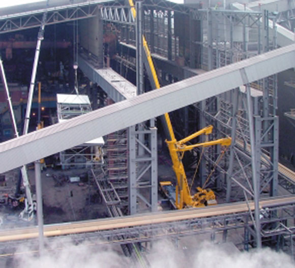 Rowecord Engineering has altered and extended Corus’s Concast facility at Port Talbot in South Wales.
Following Rowecord Engineering’s successful reconstruction of the No. 5 Blast Furnace at Corus Port Talbot, the company was awarded a contract to alter and extend the Continuous Casting Facility (Concast) there. This, too, is a fundamental part of the steelmaking process. The project involved the design, detailing, manufacture and erection of around 6,000 tonnes of structural steel. The need to minimise the impact of the work on the existing plant created a predominantly modular-based approach to the project. Not a planned day of work was lost to Corus during the process, and considerable time savings were achieved for the project programme.
THE EXISTING PLANT
The purpose of the Concast Building is to house continuous casting machines (casters) and associated craneage and facilities for the production of 234 mm thick by 850-1600 mm wide steel slabs. The Concast Building is divided into three bays lengthways – the Turret Bay, Concast Bay and Service Bay. Each bay houses electric overhead travelling (EOT) cranes. The largest of these is in the Turret Bay, which houses two cranes each of 500 tonnes lift capacity. To the east of the building are a further two external bays – the receiving bay and the process bay, each with EOT gantries.
Ladles of molten steel are transferred from the adjacent Basic Oxygen Steel (BOS) plant into the Turret Bay by means of transfer cars. Each ladle is 4.9m diameter, 5.6m high and weighs around 470 tonnes when fully laden with 320 tonnes of molten steel. Once inside the Turret Bay, the ladles are picked up by an EOT crane and transported to one of the three casting machines. The ladle is lowered onto a structure called a turret which loads the ladle into the correct position for discharging the molten steel into the casting machine.
The molten steel leaves the bottom of the ladle via a nozzle and enters a tundish – a kind of mobile reservoir which acts as a buffer and allows a continuous controlled flow of molten steel to be maintained into the top of the casting machine – even when empty and full ladles are being exchanged. The molten steel passes down through a mould and is shaped by rollers housed in segments as it passes through the cooling chamber, where it is cooled by water spray before emerging as slab at the bottom. It then passes out through the service bay on rollers, where a cutting machine cuts it to length before being discharged into the receiving bay, where it is picked up by an EOT crane for sorting and onward transfer.
THE PROJECT
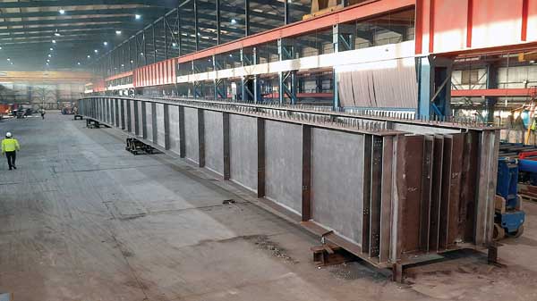
The project involved extending all three bays of the building towards the north and making internal alterations, the most significant of which required the removal of the column at grid reference JB 31 to make way for the Turret of the new Caster No 3. The removal of this column entailed replacing the existing 16m span crane girders with 32m span girders. The replacement girder supporting the 500 tonne capacity EOT crane was a 4.8m deep plate girder weighing 120 tonnes. This girder was assembled in the works as two 60 tonne units for transport to site. These were then welded together at site before installation. The project also included extending the receiving bay crane gantries to the north.
STRUCTURE
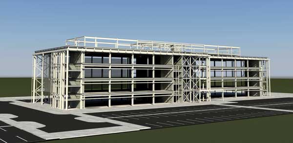
The Concast Building’s main latticed columns are typically fabricated from twin 1 m deep I-section plate girders laced together, and the largest weigh over 100 tonnes. These major structural elements carry the large vertical crane loads to the foundations and also provide transverse stability to the building by essentially acting as large vertical cantilevers. By contrast, the roof lattice girders are relatively light being made from slender angle sections.
The scale of the Concast building is impressive. At a shade under 50m internal height the building is taller than the walkways on London’s Tower Bridge (42m) and the footprint of the extended facility covers the area of nearly four football pitches. The 500 tonne capacity cranes in the Turret Bay each actually weigh around 1,500 tonnes when fully laden – equivalent to the weight of three and a half fully laden jumbo jets.
PLANT
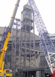
Across the north end of the existing building ran the 633 Conveyor – a strategically vital artery transporting 200 tonnes per hour of raw materials and additives into the BOS plant. It was necessary to divert this conveyor some 30m north to make room for the building extension, with a shutdown period of only three days. This was achieved by constructing a new line of conveyor on new towers and trestles, before diverting the lime flow, and then dismantling the old conveyor structures. An adequate supply of water is essential for the Concast operation. Emergency water for Caster No. 2 was stored in three tanks mounted on a 45 m high steel tower at the north end of the existing building adjacent to the 633 conveyor. This tower was relocated about 100m to the north and switched to serve the new Caster No. 3, a new one having already been built at the new location to serve Caster No. 2. Rather than dismantle and re-erect the existing tower it was lifted to its new location in one piece and complete with water tanks using a 1,200 tonne capacity crane. Prior to the lift, full structural design checks were carried out and temporary bracing installed to ensure stability at all times. A new water treatment plant was constructed to the north of the BOS plant to provide water of the right quality.
CONSTRUCTION
It was vital to maintain production during the construction period, so there were many logistical constraints, such as the positioning and operation of cranes. The site was operated under the COMAH (Control of Major Accident Hazard) regulations and considerable construction planning and design effort went into enabling maximum use of pre-assembly of elements at ground level before erecting the resulting structural modules. This strategy minimised the number of lifts and the amount of erection work carried out at height, with consequential cost, programme and health and safety benefits. Careful consideration was given to all stages of handling, turning and lifting of major items and lifting lugs, and lifting beams and frames were designed where required.
Inside the extended north end of the building the new Casting Machine No. 3 is being constructed. The turret is mounted on a large concrete block, adjacent to which is a steel floor structure 44m x 36m on plan, situated 13m above ground level (the caster floor). Built into the floor are tracks to take special cars to allow tundishes to be moved rapidly into position over the top of the mould. The tundishes are removed for cleaning out after about eight hours or so, and the pair of tundish cars allows a fresh tundish to be exchanged quickly for a used one to enable continuity of the casting process.
PROGRESS
Pre-engineering work started on site in late 2003 with main site works starting in early 2004. Commissioning is due to take place early next year so that the new slab caster becomes fully operational during the second quarter of 2005. The successful outcome of the project will enable Corus to increase output of steel slab from 3.7 Lifting and relocation of the existing water tower, in one piece. million to 4.7 million tonnes per year.
AUTHOR
Paul Benwell, Technical Director of Rowecord Ltd

