Technical
Designing portal frames
Portal Frames account for some 40% of structural steelwork used in the UK, but they are far from simple structures. David Brown and Martin Heywood of the Steel Construction Institute highlight some of the key design issues.
Portal frames are familiar to us all. Large spans, low pitches, and used throughout the UK. Portal frames account for around 40% of structural steelwork used in the UK, and are common enough to have their own special rules in BS 5950. Often, portal frames are designed using software specially written for that form of construction. Tempting, then, to assume that the design of portal frames is simple. On the contrary, portal frames involve most types of structural phenomena that designers might meet, all in the one structure. This article highlights some of the more important design issues that should not be overlooked. Familiarity should not lead to inattention!
Restraint at the column top
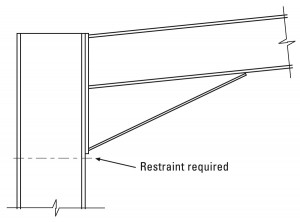
It is essential that the inside flange of the column be restrained where the column meets the underside of the haunch, as shown in Figure 1.
This requirement is simply to prevent that point buckling out of plane under the massive compression forces present. Often the column will be at or very near its full moment capacity, with a keen desire to buckle. Regrettably, it is not uncommon to see frames without a restraint at this point. If the restraint is to be provided by knee (or ‘fly’) bracing, then a side rail must be provided at this level. This can seem uneconomic, as the sheeting can often span to a side rail located at a much lower level, but the importance of a restraint at that level cannot be over-emphasised.
The original research and the code clauses expect a restraint at that point. If restraints are provided at a lower level in the column, and at some point along the haunch, it may appear that the region is restrained. There is no clause in the Standard that describes how members under a large bending moment and incorporating a massive change in direction are to be designed, however.
Restraints around the frame
In completed structures, the system of restraints to the inside flange is often interesting, and is a good indicator of how well the structural mechanics has been understood. In the gravity load case, the inside of the frame in the eaves region is in compression, and the inside flange of the column, haunch and rafter will need restraining – often by fly bracing. The moments in this region are high, and several restraints are likely. Toward the apex, the outside of the frame is in compression, but here the purlins automatically restrain the compression flange.
In the wind uplift cases, the region near the apex has compression on the inside flange, and often restraints are needed. Compared to the eaves region in the gravity load case, the moments are lower, and fewer, more widely spaced restraints are usually sufficient. A typical layout of restraints is shown in Figure 2. If restraints seem to be provided every second purlin as if by default, one might question the reason.
In Figure 2, a restraint is provided at an intermediate side rail. The rail does need to be continuous – if the elevation is perforated by roller shutter doors and the side rails are in short lengths between the door posts, it is unlikely that fly braces to the column are effective. At the design stage, it is likely that the section size of the column must be increased, until it has sufficient resistance without intermediate restraints. In look-up tables, this condition is sometimes described as ‘unrestrained’.
Relative size of rails and purlins
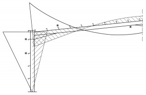
Years of experience have demonstrated that at reasonable spans, the combination of UB members and light gauge rails and purlins perform entirely satisfactorily. Designers should be alert to longer spans, where the same proportions of members may not be maintained. Long spans produce large moments, which demand large members. The compression force in the flange which must be restrained is large. However, if the frames are still provided at ‘normal’ bay spacing, the purlins and rails will not have grown in size from more modest spans. It is easy to envisage a situation where the stiffness of the secondary member is insufficient to provide the necessary ‘U-frame’ action, even though locally the fly bracing has a firm grip on the flange. The potential buckled form is shown in Figure 3. This is only a risk at large spans – and need not be considered for normal construction
In-plane stability
All steel-framed buildings need to be checked to ensure that they have adequate in-plane stability and single storey portal frames are no exception. BS 5950-1:2000 contains specific recommendations for portal frame stability, which can be found in Clause 5.5.4. The rules for multi-storey frames given in Clause 2.4.2 should not be used for portal frames.
Three alternative methods are presented:
- The Sway Check Method
- The Amplified Moments Method
- Second Order Analysis
Of the three methods, the Sway Check Method is the simplest and will normally be the designer’s first choice. In essence, the method involves little more than applying Notional Horizontal Forces at the top of each column and calculating the corresponding deflections. However, there are a number of pitfalls that are worthy of comment in this article.
a) Geometrical limitations – BS 5950-1:2000 places limitations on the use of the Sway Check Method relating to the geometry of the frame. It is essential that these limitations are observed, as trial calculations carried out at the SCI have demonstrated that the Sway Check Method is unreliable outside these limits.
b) Calculation of Notional Horizontal forces – The Notional Horizontal Forces (NHF) should be calculated as 0.5% of the vertical reaction at the base of each column. This is subtly different to the NHF used in checking the stability of multi-storey frames. The NHF used for portal frames should be applied as separate horizontal point loads at the top of each column and should include the vertical component of the wind loading where appropriate.
c) Load cases – Since the 2000 revision of BS 5950-1, there has been a requirement to perform the Sway Check in all load cases (previously it was only used in the gravity load case). Whereas it is possible that the required load factor λr for the gravity load case will be 1 (if the height/1000 check is passed), λr for load cases including wind will always be greater than 1. In practice however, the wind load cases rarely govern the design of the frame, so it is unlikely that heavier members will be needed as a result of λr.
d) Use of formulae – As an alternative to applying the NHF and calculating the horizontal eaves deflection, BS 5950-1:2000 presents formulae that may be used to determine λr. Designers should note that these formulae are no more accurate than the use of the NHF; i.e. frames that fail the height/1000 check will not pass the corresponding formula check.
Whichever method is used, designers are advised to take advantage of the column base stiffness, as this will increase the in-plane stability of the frame (reducing the deflection in the Sway Check Method or increasing λcr in the Amplified Moments Method). For nominally pinned bases, BS 5950-1:2000 permits the use of a base stiffness of 10% of the column stiffness when checking frame stability. Furthermore, there is no need to design the foundation for the base moment arising from this stiffness, provided that the base is assumed to be a true pin (i.e. zero stiffness) for all other ULS checks. Designers will also find it useful to allow for the base stiffness when carrying out the SLS deflection checks. In this case, a base stiffness of 20% of the column stiffness should be used.
Purlin and cladding considerations
The changes to the requirements of Part L of the Building Regulations over recent years have resulted in building designers paying more attention to the cladding than ever before. In the past, these changes have involved increasing the insulation thickness, resulting in the weather sheet and liner of built-up systems becoming further apart and all forms of roof cladding becoming heavier. With the insulation thickness now reaching a point where further increases will result in diminishing improvements in performance, greater emphasis is now being placed on air tightness with the promise of strict enforcement of the regulations through on-site testing. There are two issues that designers should be aware of:
a) Purlin restraint – It is common practice in the United Kingdom for designers to select the required purlin size from the manufacturer’s load/span tables. The capacities presented in these tables are usually based on the assumption that the purlins will be fully restrained in the gravity load case and partially restrained against wind uplift. The load capacities have in the past been determined by full-scale tests. However, the increase in insulation thickness in recent years has reduced the level of restraint offered to the purlins by the cladding system and designers should check with purlin suppliers that their test results and calculations remain applicable for the proposed cladding system and insulation thickness.
b) Position of purlin flange – With the air leakage requirements becoming ever tighter, accurate installation of the cladding is essential. The quality of the installation will naturally depend in part on the care with which the contractors carry out their work, but it can also be influenced by the condition of the supporting steelwork. In particular, excessive sag of the purlins in the plane of the roof slope can present difficulties when it comes to fixing the cladding. To avoid any such problems, it is important that consideration is given at the design stage to the method of working on the roof and that the assumptions made at this time are realised on site. For example, operatives should not walk on unrestrained purlins unless they have been specifically designed for this loading.
The SCI is currently engaged on research in this area and further guidance on the specification and installation of purlins and cladding will be published later this year.

