Technical
AD 437: Curtailment of transverse bar reinforcement in composite beams with steel decking designed using Eurocodes
The purpose of this Advisory Desk Note is to provide guidance on the curtailment of transverse bar reinforcement in slabs on composite beams with steel decking, designed to EN 1994-1-1. Such information was previously presented in AD 325, for design to BS 5950-3.1, but the provisions in EN 1994-1-1, and the clauses in EN 1992-1-1 to which it refers, give more explicit coverage of this topic than the BS rules. The approach to transverse bar curtailment is therefore different.
The transverse reinforcement is provided to transfer longitudinal shear force from the steel beam, via the shear connectors, out into the effective breadth of the slab. Transverse bar reinforcement may be needed to supplement the resistance of the mesh in the slab, and these bars must extend a sufficient distance from the beam centreline.
Internal beams
A fundamental difference between EN 1994 and BS 5950 is that the former adopts a so-called ‘strut and tie’ model, through which shear resistance is determined from consideration of concrete struts in compression and reinforcement ties in tension. A component of the force in the struts resists longitudinal force in the slab, and the component transverse to the beam axis is resisted by the reinforcement.
For composite beams with decking spanning perpendicular to the longitudinal axis of the beam, the critical transverse shear plane is adjacent to the steel flange. However, for decking running parallel to the beam the critical plane is normally in the nearest crest in the decking to the shear connectors (see Figures 1 and 2).
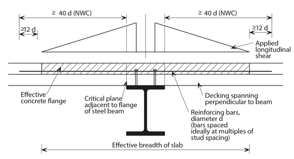
Figure1: Assumed pattern of transverse shear stresses and anchorage lengths, beam with transverse decking
When considering the need for bar anchorage beyond these critical planes, for design to BS 5950, AD 325 made certain assumptions (with both a simplified and rigorous model) about how the force in the slab decreases across the effective width. The Eurocodes remove the need for such assumptions by providing explicit guidance:
- EN 1994-1-1, 6.6.6.2 makes reference to EN 1992-1-1, 6.2.4
- EN 1992-1-1, 6.2.4 (7) states that the reinforcement should be anchored beyond the strut requirement (see EN 1992-1-1, Figure 6.7)
- EN 1992-1-1, 8.4.4 defines how to determine anchorage length
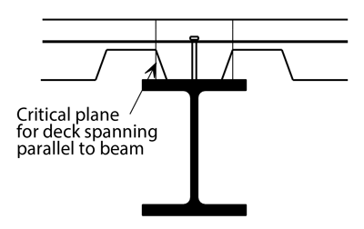
Figure 2: Critical plane for deck spanning parallel to beam
With reference to Point 2, determining the location that corresponds to ‘beyond the strut requirement’ is not obvious, particularly given that different angles can be chosen for the struts in what can be an iterative procedure. As a (slightly) conservative simplification, the point beyond which anchorage is needed may be assumed to be the critical planes, as defined above. This also results in an approach that is common to that used in design to BS 5950.
Point 3 refers to clauses that consider the tensile strength of the concrete, the strength of the reinforcing bars, and a number of other parameters. For typical bars in typical concrete the result will be a need for an anchorage length similar to the familiar value of 40 d (where d is the bar diameter). When lightweight concrete is used greater anchorage lengths are required, as a function of the concrete oven-dry density (see EN 1992-1-1, 11.3.1). Should larger bars be chosen than are necessary, such that they are stressed below yield, shorter anchorage lengths will suffice.
Although the Eurocode methodology makes no reference to the effective breadth of slab in the context of transverse shear resistance, this nevertheless remains an area of concrete subject to significant in-plane stresses. In the absence of a more rigorous analysis where a number of planes are considered rather than just the critical plane (which would most likely show that mesh alone is sufficient in the outer reaches of the effective breadth), we therefore recommend that the bars extend at least 12 d beyond the effective breadth. This is also in keeping with BS 5950 practice (AD 325 Simplified Method)
It is important to note that when the decking is perpendicular it may contribute to the transverse reinforcement needed, but when the decking is parallel it cannot be taken into account (it has no ‘in-plane’ tensile resistance so cannot contribute in a strut and tie model).
Edge beams
Notwithstanding differences in the definition of anchorage length, EN 1994-1-1, 6.6.5.3 contains detailing guidance for edge beams that aligns with that given in BS 5950-3.1:
- If the edge of slab from the centreline of the nearest shear connectors is less than 300 mm then place U-bars around the shear connectors
- Where headed studs are used, the U-bars must have a diameter not less than half that of the studs, and the distance from the edge of the slab to the centreline of the nearest studs should not be less than 6 ds (where ds is the stud diameter)
Contact: Eleftherios Aggelopoulos
Tel: 01344 636555
Email: advisory@steel-sci.com

