Technical
AD 410: Pouring concrete to a constant thickness or to a constant plane
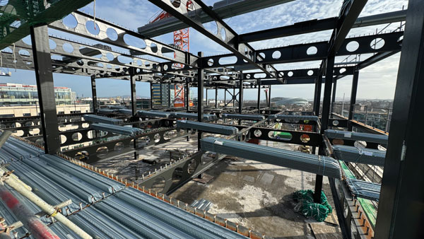
Composite flooring systems comprising concrete and profiled steel decking supported by a grillage of primary and secondary steel members are a popular form of floor construction. The in-situ concrete acts compositely with the steel decking which acts as permanent formwork for the concrete and as external reinforcement to the composite slab. This AD Note is an update to guidance given in AD 344 ‘Levelling techniques for composite floors’ and reflects the most recent practice in pouring concrete to a constant level or thickness. However, the guidance in AD 344 is still valid.
For composite flooring systems the concrete can be poured to a constant thickness or to a constant plane. The type of floor construction is one of the issues that must be determined at the design stage and it is important that this is communicated to the concrete contractor. This AD Note describes the two methods that may be used to pour the concrete (constant plane or constant thickness), the expected surface finish (flatness and levelness) that may be achieved, the construction loads that should be taken in to account during design and the means of communicating the method of concreting to the concreting contractor.
1.0 Design considerations
An important design issue is to decide if the concrete is poured to a constant thickness or to a constant plane as the method of construction will affect the deflections of the steel decking and the steel frame and the amount of concrete placed. The two methods for concreting are:
- Pouring to a constant thickness and,
- Pouring to a constant plane
1.1 Constant thickness
Concreting a floor to a constant thickness can be achieved by using permanent proprietary formed tied construction joints, levelling pins (which are supported by either the steel decking and beams or the steel decking alone) or a depth gauge. The term ‘Structural floor level’ refers to the case where the screed rails etc. are supported by the steel decking and beams and the term ‘Constant depth’ refers to the case where the depth gauge or dip method is used. Both of these approaches are described below.
a. Structural floor level. In this approach the reference points defining structural floor level are supported by the steel decking and beams at the design slab depth from the decking profile. The reference points are usually placed as close as possible to the beam centre-lines to avoid excessive displacement during concreting. However, they will drop as the decking and beams deflect as concreting proceeds. The slab thickness will remain as defined by the reference point and deck levels but the finished profile will not be the same as the original position of the reference points. This method should give reasonable control over both the concrete thickness and flatness (but not levelness). This method will result in additional concrete (ponding) at mid-span decking regions as a result of deck deflection between the reference points.
b. A constant depth using a depth gauge. In this approach the reference point is a rod with the constant depth set off the steel decking so that the top profile will be parallel to the decking profile. Good control of thickness should be achieved but the finished surface profile will depend on the initial profile and subsequent deflection of the steel deck and supporting beams. This is typically the recommended method and should always be used where the beams are pre-cambered.
1.2 Constant plane
In this method the finished concrete level is determined using a staff and level, often a laser level. As levelling is to a constant reference plane, any deflection of the steel decking and supporting beams as the concreting proceeds can give rise to a considerable increase in the slab thickness and the volume of concrete placed. Additionally, previously levelled areas may drop as the supporting beams continue to deflect as adjacent areas are concreted. The fresh areas of concrete will continue to be levelled to the reference plane therefore small localised variations in level and flatness can occur across the slab pour. It is difficult with this method to achieve good control of level to datum, flatness and thickness. Using this method the slab thickness can be considerably thicker than designed due to the compound deflection of primary beam, secondary beams and steel decking. This depends on the centres and stiffness of the supporting beams.
1.3 Tighter tolerances on level
If tighter tolerances on floor level are required consideration should be given to providing a stiffer grillage of supporting primary and secondary floor beams. This will result in a combination of larger steel sections, short deck spans, more frequent beams and/or columns and possible a heavier gauge steel decking profile. Where strict control of floor level is required it is suggested that the deflection of the steel under construction loads is limited to 10mm. This approach is often considered uneconomic.
Alternatively propped construction may be used to reduce deflections during construction. However, use of propping should be considered at the design stage and not used as an afterthought on site. When a composite slab is propped during construction there is a higher demand on the shear connection between the decking and the concrete than in an unpropped slab, as a propped slab has to support the self-weight of the concrete through composite action. Consequently, a propped slab will have a higher degree of creep deflection under imposed loads than an unpropped slab, as well as the additional deflection of the decking under the self-weight of the concrete. A higher percentage of reinforcement must be specified for propped slabs to limit cracking over the supporting beams, and this clearly needs to be specified at the design stage.
Consideration should be given to deflections after the props are removed.
2.0 Construction loads
Clause 9.3.2(1) of BS EN 1994-1-1 gives recommendations for the actions to be considered during construction when the profiled sheeting is acting as permanent formwork. The following loads should be taken into account:
- Weight of concrete and steel deck,
- Construction loads including local heaping of concrete during construction, in accordance with clause 4.11.1 of BS EN 1991-1-6,
- Storage load, if any,
- ‘ponding’ effect (increased depth of concrete due to deflection of the sheeting)
Clause 3.2.2 of Technical Report 75 ‘Composite Concrete Slabs on Steel Decking’ by the Concrete Society [4] gives further information on the loads to be considered during concreting.
With regard to ‘ponding’ clause 9.3.2(2) of BS EN 1994-1-1 gives the following recommends:
‘If the central deflection ,δ, of the sheeting under its own weight plus that of the wet concrete, calculated for serviceability, is less than 1/10 of the slab depth, the ponding effect may be ignored in the design of the steel sheeting. If this limit is exceeded, this effect should be allowed for. It may be assumed in design that the nominal thickness of the concrete is increased over the whole span by 0.7δ.’
Pre-cambering of beams is sometimes used to decrease the deflections from construction loads. Where pre-cambering is used, Clause 5.4 of Technical Report 75 [4] recommends that the composite floor slab is poured to a constant thickness. Unless the constant thickness method is used there is a risk that there will be insufficient cover to the mid-span of the beams should the camber not fully ‘drop out’. Traditionally, engineers have specified a pre-camber of only ²/₃ to ¾ of the calculated simply supported deflection of the beam, or up to half the concrete cover to the decking (whichever is less). Doing this will greatly reduce the risk of a thin slab when the other methods of concreting are used.
3.0 Flatness and level tolerances
The main consideration with regards to the specification of tolerances is the building’s use; buildings where the finished slab is to provide a wearing surface may require tight level and flatness tolerances, whereas buildings where subsequent finishes are applied such as office structures may not. The requirements in the specification need to be achievable: it is not possible to construct a composite slab to very tight level tolerance because of the deflections of the beams. However, tight tolerances are not necessary for most applications, and deviations can be taken up with screeds, levelling compounds or a raised floor. Where isolated areas in a building have more onerous flatness requirements, they can be achieved by using levelling compounds or screeds locally. Extensive grinding should not be used to modify flatness, as it can significantly reduce the slab thickness.
For the rare occasions where levelling compounds and screeds cannot be used, and tight level and flatness tolerances are required, the supporting beams will need to be designed to limit deflections to values which correlate with the required top surface tolerances. This could have significant implications for the cost of the beams.
The following general tolerances for levels are given in references [1], [2] and [3], relative to the level of the datum (normally structural floor level):
- ±15mm on top surface of concrete measured at a column
- ±10mm on top surface of supporting steel beams at a column position
The slab thickness tolerances at a column position will be about ±20mm using the above values. Further information on level and flatness tolerances can be found in reference [4].
4.0 Information required for the casting of the concrete
Where projects are working to the Construction (Design and Management) Regulations 2015 it is the responsibility of the Principal Designer to make sure the right information is given to those that need it prior to concrete pouring work commencing. If the Construction (Design and Management) Regulations 2015 do not apply to the project then the Main Contractor will need to ensure those contracted to carry out the concrete pouring are provided with this information.
To avoid overloading the decking and supporting steelwork during the construction phase it is recommended that the method of concreting (constant level or constant thickness) is communicated to the concreting contractor on the scheme designer’s construction drawings.
Whilst acceptable flatness (surface regularity over short distance) can be achieved, a level slab (level to a defined datum over large distances) can only be achieved where this has been considered early in the design of the steel frame with beam spacings, deck spans and deflections considered accordingly. Extensive guidance on this subject can be found in reference 4
5.0 References
- British Standards Institute, BS EN 13670. Execution of concrete structures, BSI, London 2011.
- British Standards Institute, BS 8204-2. Screeds, bases and in situ floorings. Part 2: Concrete wearing surfaces. Code of practice, BSI, London, 2003.
- The Concrete Society. Concrete industrial ground floors. A guide to design and construction, Technical Report 34, 4th edition, 2013 (revised March 2016).
- The Concrete Society. Composite concrete slabs on steel decking. Guidance on construction and associated design considerations, Technical Report 75, 2016
Contact: David Moore
Tel: 020 7747 8122
Email: david.moore@steelconstruction.org

