Technical
AD 366: Bolts and Pins – Background information ASM 22.3.12
This advisory desk note provides background information on the design issues for bolts and pins, and why there are different design rules for each component.
The differences between a bolt and pin are:
• Pins may be designed to rotate
• Pins may be designed to be removed
• Bolts and pins have different clamping effects on the connected plies.
BS 5950-1:2000 (Aug 2007) intends a “pin” to cover anything from the spindle of a bridge bearing to a simple dowel, that have little or no clamping effect on the connected plies. A shouldered bolt, a fitted bolt, a threaded rod or a round bar with nuts both ends (whether fully threaded or not) would all be understood as bolts, with the potential to clamp the plies together.
A pin is unthreaded and is only prevented from coming out of the hole by ancillary means such as caps or dowels; the assembly has little or no clamping effect on the connected plies. A pin may be relatively long compared to its diameter which is why a check on moment capacity is included in clause 6.5.3.4 of BS 5950-1 and a combined shear and bending check of pins is included in Table 3.10 of BS EN 1993-1-8:2005 (Aug 2010).
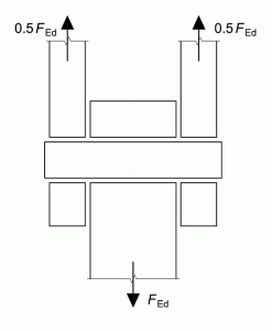
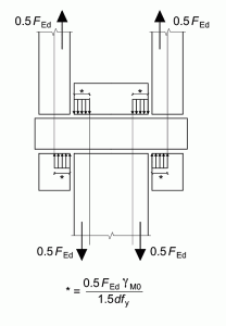
Clause 3.13.2(2) of BS EN states that “generally” the reactions between the pin and the connected parts are uniformly distributed along the length in contact on each part. This method shown in Figure 3.11 of BS EN 1993-1-8 (Figure 1 below) to calculate the bending moment is rather conservative (see AD 172: Bending moment in a pin, which demonstrates how the expression in the Eurocode was derived), particularly where the plates are relatively thick. Unfortunately, the Clause does not say when or how the general rule may be modified. A less conservative approach is to reduce the length in contact (required for load transfer) based on the bearing stress as specified in Table 3.10, which will result in a reduced bending moment.
This option means that a force distribution as shown in Figure 2 below (similar to Figure 3.6 of BS EN 1993-1-8) may be assumed, rather than the conservative distribution shown in Figure 3.11 of the Standard. The simple approach illustrated in Figure 3.11 is conservative.
Contact: Abdul Malik
Tel: 01344 636525
Email: advisory@steel-sci.com

