50 & 20 Years Ago
50 Years Ago: The New Cambridge University Press

Construction work on the warehouse and machine block. The use of structural steelwork enabled this unusual flared arch to be built with considerable economy
Low cost, high speed of erection and light weight were among the principal considerations which led to the choice of structural steelwork for the two large production blocks of the new Printing House now under construction for the Cambridge University Press. Situated on the outskirts of the town, the new premises will bring together the entire staff and printing equipment now housed in outdated buildings in the centre of Cambridge. Total cost of the new printing works will be about £1 million, and some 1,000 tons of structural steelwork will be used.
All the buildings are planned on a 12-ft module to provide integration between the production and the office areas and to simplify planning in the main factory blocks. Continuity between buildings is emphasised by the use of white and black mosaic finishes though variation is provided by means of aluminium sheeting to the production blocks contrasting with glazed curtain walling and occasional brick panels in the office blocks.
The largest single block is the machine and warehouse area, 33 ft long by 288 ft wide, which is covered with a roof of a curved and folded shape. The choice of roof structure for this main area was determined by several factors, the more important being:
1 Provision of clear spans of 144 ft. – only 1 row of columns within the building.
2 An interesting roof profile for aesthetic reasons.
3 Stanchion centres on a 24-ft. module.
4 External stanchions to be no wider than 12 in. on face when cased.
5 A clear space within the roof to be provided for air conditioning ducts and the numerous other services.
6 Continuous glazing to be provided on all sides, broken only by the columns.
7 Reasonably economic solution.
From consideration of point 5 it was obvious that most forms of trusses with diagonals were to be avoided, otherwise this would encroach on the intricate service layout and therefore an arch or shell form of construction was to be preferred. These designs also had the merit of being curved, thus giving an interesting appearance to the exterior (the interior being hidden by a false ceiling.)

Interior of warehouse and machine block. Note the steelwork for the curved roof.
Both concrete shell production and structural steelwork were considered for the scheme, and structural steelwork was preferred on the basis that, in addition to being considerably cheaper, it offered the same advantages since the appearance from the outside would be identical. Steelwork, also having the advantage of being lighter, necessitated smaller foundations; was faster to erect and less dependent upon weather conditions than a concrete shell.
The roof design chosen is a 144-ft. span lattice arch designed using normal British Standard mild steel angle purlins. The springing of every alternate truss is raised 7 ft. 6 in. to give a folded appearance to the roof. The secondary purlins running in the direction of the curve are only 2¼ in. by 2¼ in. by ¼ in. angles and although these were supplied straight they were quite easily bolted into position by hand to give the design curve. The arches themselves are built from two pairs of 6 in. by 4 in. by 5⁄8 in. angles back to back, laced together with 2 in. by 2 in. by ½ in. angles to form a lattice compression boom, and pinned down at crown and at supports. The bottom tie of the arch consists of two 8 in. by 3 in. channels back to back with vertical steel angle hangers to support it from the boom above.
A three-pinned arch was preferred to the two pinned variety because it did not involve any cost penalty and simplified erection. To give lateral support to the two compression members in the lattice arch, it was necessary to use lattice purlins made from angle sections top and bottom and a ¾ in. diameter bent mild steel rod welded between them, the bottom legs being inclined at the ends to support the lower pair of boom angles.
Expansion of the 32 arches – each weighing 8½ tons – is allowed for by use of phosphor bronze sliding plates under each truss at the internal stanchions and by the use of double trusses at the centre of the building with a ½ in. expansion joint between them. Torshear high-strength friction grip bolts were used in the joints of the arches.
It was not considered desirable to transfer any wind load to the crowns of the arches at the gables and, therefore, the wind of the gable is carried by a horizontal wind girder a ceiling level which spans between stanchions, and the reactions at the end of the wind girders are transmitted to the centre and side rows of stanchions by means of an R.S.J. at eaves level. This eliminates the need for bracing in the end bay which would appear unsightly in view of the fact that the glazing is continuous around the sides of the building.

Aerial View of the new Cambridge University Press. In the foreground is the machine and warehouse area
Owing to the fact that the roof is inclined, its shape is elliptical, although the main trusses are circular in section. This posed some problems in the use of steel decking since the angle at the end of the sheets increases towards the end of the roof. However, it was considered that the radius (174 ft. 6 in.) was large enough to keep the difference between straight cut sheets to an acceptable minimum, and this worked out quite satisfactorily in practice. The roof covering is in galvanized steel deck of trough sections with 1-in cork insulation finished with mineralised roofing felt.
The other large single area – the composition block – is 192 ft. 0 in. wide (comprising two 96 ft. 0 in. span lattice girders) by 228 ft. 0 in. long. It, too, is entirely steel framed. There are 38 girders at 12 ft. 0 in. centres, each weighing 3 tons. A plate girder, or welded construction, 85 ft. 0 in. long by 6 ft. 6 in. deep, weighing approximately 12 tons was delivered by road in one piece.
This building did not present so many design problems and as the use of diagonal truss members was permissible, due to a reduction in the air conditioning services, the normal ‘N’ truss was used to form a butterfly shape in elevation. The roof covering is similar to the other main production area.
The foundation problems associated with the site were those of a high ground water level and the presence of soft brown clay substrata overlaying gault clay.
The soft brown clay, after analysis, revealed that appreciable settlement was to be expected and it was incapable of sustaining any great load. Consequently, if spread foundations were to be used, they would need to be taken down to below ground water level. This would have involved costly excavation in water and also raised the problem of differential settlement due to the large variation in column loadings.
In view of these difficulties, piled foundations were used in all the buildings.
Architects responsible for the project are Beard, Bennett, Wilkins and Partners; Consulting Engineers, Frederick S. Snow and Partners.

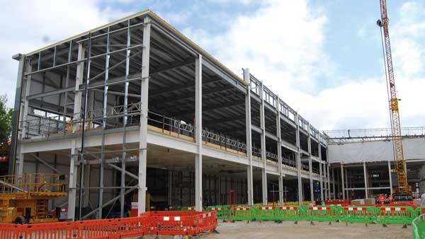
Interior of composition block, showing standard end trusses

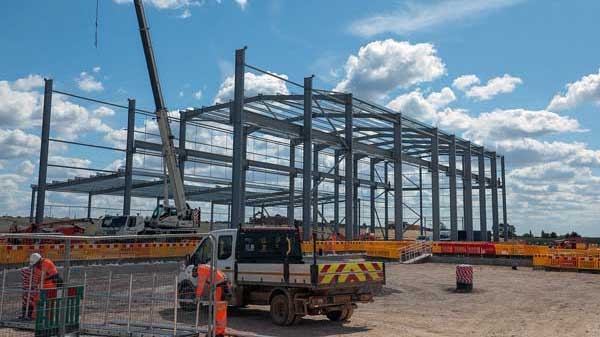
Structural steelwork for the machine and warehouse area